Why Data Driven CAD is Preferred over File Based CAD

The need for PLM integration with CAD is one of the key concerns of any engineering company to stay competitive and launch the product in the market in a short duration.

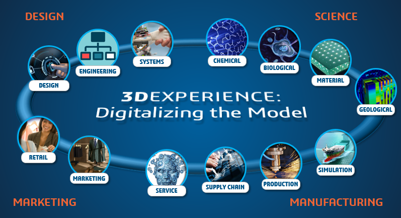
If you are in the process of replacing your file-based CAD system with data-driven CAD, then Dassault Systèmes’ 3DEXPERIENCE platform is the way to go.
CAD blog1

3DEXPERIENCE platform boasts of distinct features like cloud based, data driven and all-in-one PLM experience which will ease any typical workflow and support faster go-to market strategy.

3DEXPERIENCE is available on Premise and also on Cloud. This eliminates file-based data storage which has an impact on real time digital continuity.

One of the unique values of having database driven CAD system is that it gives access to store the data in the server and thereby restricts saving it locally. All the stakeholders can access the data based on their roles which is assigned by the admin. It also allows external suppliers and customers to connect to the platform, access relevant data, collaborate and accomplish the task thereby expediting decision making.

CAD blog2

Often many projects get delayed or overshoots budget because of the discontinuity of the digital data flow. The major advantage of a data driven platform is to access a “single source of truth” which means if any data is modified, then it is available for all the stakeholders in real time. They will always have the access to updated data.

Imagine that there are multiple work locations and team members working on the same project. Any changes in part or assembly will automatically be updated to all the stakeholders no matter where they are working.

Analysis is one of the crucial areas which can accelerate the product launch. More often, products are validated in a digital platform instead of a physical test. In this scenario, design data should be imported to analysis software and any change in the design has to be communicated to the design team. Once the design changes are done, the design team needs to push data to analysis software manually. This process often leads to data loss and is also time consuming. However, with 3DEXPERIENCE platform, all the stakeholders of the project (analysis team is also one of the stakeholders) can get real time data without any data transfer out of the platform. Since the data is stored in server, all the users will have access to the latest data with respect to the assigned project.

The CATIA 3DEXPERIENCE platform is much more than a CAD software. It also manages end-to-end workflow, deliverables and project deadlines. Since the platform is data driven, project managers can access all the data which is related to the project and make better decisions so as to accelerate the product launch to the market.

3DEXPERIENCE has two different interfaces: web and native interface. Social, collaborative and information intelligence apps will work in web interface without any installation. The native apps however require installation. All the 3D modelling and simulation apps such as CATIA, SIMULIA and DELMIA are part of native apps.

Today the market is more demanding and competitive. 3DEXPERIENCE will definitely help companies to stay competitive and create sustainable growth.

How to perform Geotechnical Analysis of Soil using ABAQUS

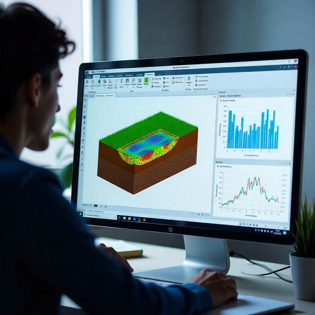
The analysis of geotechnical problems is rather complex due to stress dependent material behavior and varying stiffness for loading and unloading conditions. Generally, soil has three different phases which are soil skeleton, pore air and pore water which often lead to complex interaction mechanism. Also, large deformation of soil continuum is observed under loading. Such complex behavior, boundary and material modelling can easily be found out and addressed by ABAQUS.

This blog mainly focuses on ABAQUS capabilities of soil modelling, material modelling, complex loading analysis, boundary modelling and analysis procedures used in geo-mechanics by taking the example of a laterally loaded pile.

Characteristics of Soil:

How to perform Geotechnical Analysis of Soil using ABAQUS-1

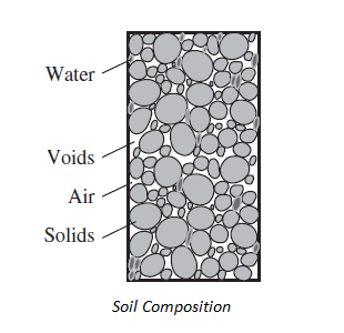
The typical granular soil composition is of three components viz solid, liquid, and gas. The solid components of soil are solid grains (resultant of weathered rocks). The liquid component is usually pore water (pore fluid), and the gas component is usually air. The gaps between the solid particles are called voids.

When soil is loaded, the pressure in pore fluid gets modified due to which the pore fluid flows and leads to the deformation of soil over a period of time. This deformation of soil can be analyzed by using mechanical and permeability properties of soil along with pore pressure boundary condition in ABAQUS.

Loading Conditions:

Material behavior of the soil is rather complex when compared with other engineering materials. Soil can be differentiated like granular soil (sand and gravel) and soft soil (clay or silts). When granular soils are loaded slowly, there will be a change in volume which results in excessive pore pressure that dissipates rapidly due to high permeability and is called as “Drained Loading”.

On the other hand, when soft soils are loaded, it generates excess pressure which is entrapped inside the pores because of low permeability. This condition is known as “Undrained Loading”. Generally, both loading conditions can be carried out in laboratory by using Tri-Axial test setup. Therefore, in numerous simulations, this complex behavior has to be taken into account.

Material Models:

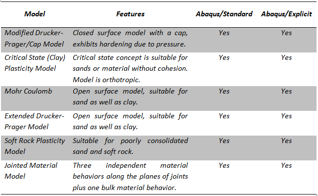
Several material models are available in ABAQUS including elastic, plastic, pore fluid, concrete damage plasticity, concrete smeared cracking and plasticity models as discussed below.

How to perform Geotechnical Analysis of Soil using ABAQUS-2

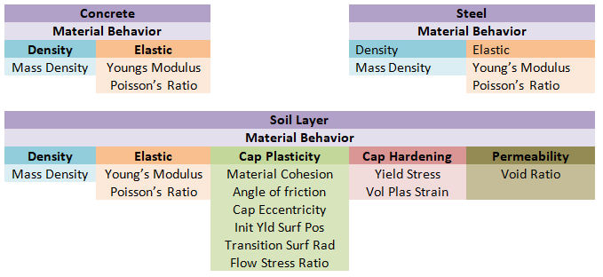
ABAQUS built-in material model can deal with applications where fully coupled conditions are needed to simulate. There are exceptions where large deformation needs to be modelled with special techniques such as Discrete Element Techniques (DEM). Also, user defined material can be incorporated with VUMAT, UMAT framework. For laterally loaded pile, the following properties are used.

How to perform Geotechnical Analysis of Soil using ABAQUS-3

Contact Interaction for Geotechnical problem:

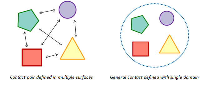
ABAQUS provides two algorithms for modeling contact interaction:

  1. Contact pair algorithm – it is used where every possible surface pair has to define contact interaction including surface which may come in self contact. It is also based on master-slave definition.
  2. General contact algorithm – it allows to define many or all regions with single interaction properties. This algorithm automatically decides master-slave surfaces.

ABAQUS also gives flexibility to find contact surface automatically within chosen parts or whole model.

How to perform Geotechnical Analysis of Soil using ABAQUS-4

In geotechnical analysis, where blast loading is carried out to analyze the structure load bearing capability, Eulerian domain needs to be defined. In such scenario, general contact has to define and it works very efficiently.

Element Selection:

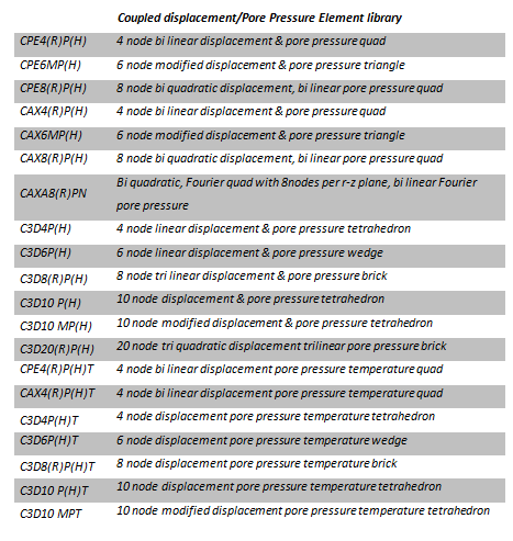
To model fully or partially saturated fluid flow through a deforming porous medium, ABAQUS provides Pore Pressure Element type which can be used for soil and geostatic analysis. These elements have both displacement and pore pressure degrees of freedom. In second-order elements, the pore pressure degrees of freedom are active only at the corner nodes. Pore Pressure Elements are available for plane strain, axisymmetric, axisymmetric-asymmetric and for three dimensional problems.

How to perform Geotechnical Analysis of Soil using ABAQUS-5

Analysis Procedure:

ABAQUS Standard provides two different procedures to analyze the soil problems viz “Geostatic” & “Soil”. Also, soil like material, in case of large deformation, can be simulated using special techniques like

  1. Coupled Eulerian-LaGrangian Techniques (CEL)
  2. Smoothed Particle Hydrodynamics Techniques (SPH)
  3. Discrete Element Techniques (DEM)

Above techniques can be used for offshore foundation, crushing of soft rocks, mining & agricultural industries respectively. For laterally loaded pile the “Geostatic” & “Soil” procedures are used for analysis.

“Geostatic” procedure is normally used as the first step of a geotechnical analysis; in such cases gravity loads, initial stress state, void ratio distribution or saturation are applied during this step. Ideally, the loads and initial stresses should exactly equilibrate and produce zero deformations. The geostatic procedure requires that the initial stresses are close to the equilibrium state; the displacements corresponding to the equilibrium state might be large. “Soil” procedure is used to specify transient (consolidation) or steady-state response analysis of partially or fully saturated fluid-filled porous media.

Material Calibration in 3DEXPERIENCE Platform

What is Calibration?

Calibration is the comparison of measurements with a standard, accurate reference. The mathematical material model is generally defined using equations. This mathematical model represents the response of the material, constitutive behaviour and parameter dependency for material behaviour. Material calibration techniques helps to achieve optimum, best fit or closest value of material laboratory test data concerning the actual material behaviour. In this blog, material calibration capabilities of 3DEXPERIENCE platform are discussed in detail.

Why Material Calibration?

The main reason behind material calibration is to avoid the challenges and lengthy process of advance material modelling in Finite Element Analysis. For example, in the case of hyper-elastic materials generally, we have laboratory test data so as to understand which strain energy potential or coefficient would be best suitable. In such a scenario, material calibration will be of help.

The manual calibration process is time consuming, difficult and might not be accurate which might lead to errors whereas the calibration process in 3DEXPERIENCE uses similar data points which are obtained during laboratory tests. It will also capture proper behaviour and reduces errors between test data and material model.

General Process of Calibration:

  1. Import the Test Data
  2. Select the material model and apply various filters
  3. Execute the calibration process

Calibration example using 3DEXPERIENCE platform:

img1

The above window shows the Calibration tab and other tab is about the imported test data. Calibration tab consists of several settings to work smoothly on imported data.

Importing and processing Test Data:

Material can be imported from CSV, XLS and text format. Units and time have to be defined and temperature can be used if needed. Input data can be processed using decimation, smoothing and zero shift option. If many data points are used, then there are chances of errors or increase in execution time. In such a scenario, decimation option can be used to define the range of data to choose for execution by defining upper and lower limits just by dragging through the plot area.

img2

Further, material model needs to be selected and the model depends on execution and numerical modes. For example, available models for numerical modes are linear elastic, hyper elastic, hyper foam, parallel rheological framework (including two-layer visco plastic) and user defined material. Analytic mode offers hyper elastic and hyper foam models.

img3

Execution mode covers variety of material models of which most of them are implemented in Abaqus. Numerical mode generally takes more time to execute over analytical but it calibrates the material as accurately as possible. Since it uses Abaqus code material subroutine, it may be slower but it covers large number of material models and is efficient. Analytical mode is faster as it uses built-in equations of mathematical models.

Correction of Imported Data:

Correction of imported data can be done through various error measure settings such as:

  1. Coefficient of Determination
  2. Mean Square Error
  3. Mean Absolute Error
  4. Root Mean Square Error
  5. Relative Square Error

img4

Along with error measure settings, there is also flexibility to choose optimization algorithms, solver settings and selection of units.

img5

Executing, Saving and Exporting Material Model:

Once the optimization control is done, material model is finalized for execution. It is possible to enter the initial and known value for material model but not necessary. Once the execution is completed, the calibration history panel appears and the selected material parameters are also updated in the calibration setup panel.

img6

The final result can be saved in the material pallet by creating a new material so that it can be used in 3DEXPERIENCE platform as and when required. Also, if execution in Abaqus is required, then the pallet can be exported as .inp file but unit selection must be done prior to exporting the data.

Conclusion:

The 3DEXPERIENCE – Material Calibration apps offer many options to calibrate the material model, specifically the new and complex material models such as hyper elastic, non-linear viscoelastic material and prony series. It is definitely a choice for faster and error free calibration.

Save options in CATIA V5

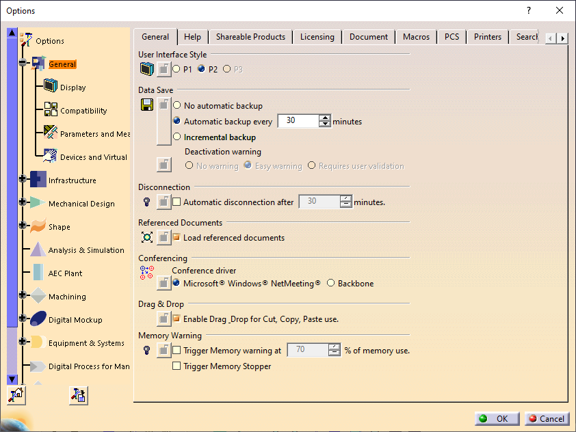
There are multiple ways to save a document in CATIA V5. It sometimes depends on organization guidelines. In this blog, multiple options of saving a document in CATIA V5 are discussed. For saving a CATIA V5 document, three options are available. Click on Tools ➜ Options ➜ General ➜ under General tab ➜ Data Save to access these options. The save options are as follows:

  • No automatic backup
  • Automatic backup every ___ minutes
  • Incremental backup

Save options in CATIA V5-1

No automatic backup

The documents here are not saved automatically.

Automatic backup

This is the option which is enabled by default and user can choose after how many minutes data should be saved automatically. It depends on the user what save frequency he wants.

The default value given here is 30 mins.

Incremental backup

This option is not available for all the workbenches. In this case, the documents that are open are stored in a directory which is temporary. It enables data recovery up to the last interaction.

Other Ways to Save a Document in CATIA

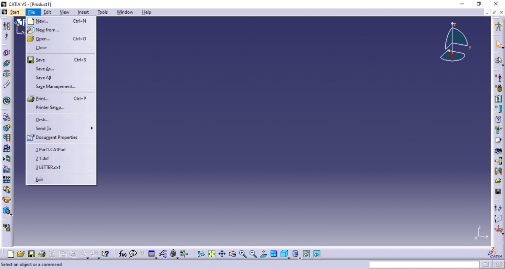
Save

This option is used to save a current file.

Save All

This option is used to save every part or product for each modification.

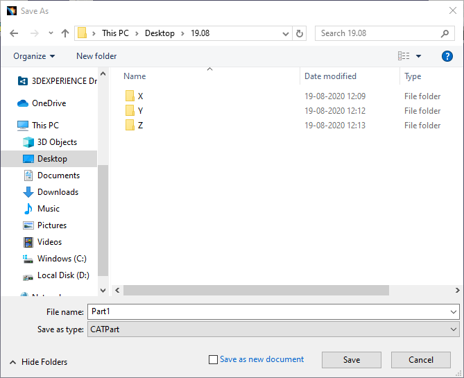
Save As

Dassault Systèmes CATIA V5 has a native part file format of CATPart but the application allows users to save the part in other formats like STEP and IGES allowing exchange of CAD data using a common file type.

Save options in CATIA V5-2

Save Management

This is used when there are complex or large assemblies to save the data storage time. The use of Save Management functions is recommended when there is a large assembly with multiple parts. The reason for this is the complexity. Using normal Save, entire model will be restored, which lengthens the data storage time in case of complex assemblies and results in large amounts of data.

Saving data using the Save Management function will save only new and modified parts. Unchanged parts will be preserved and there is no need to restore the same data. This feature shortens storage time, which is particularly important when storing large and complex models/sets on the server.

Save options in CATIA V5-3

Propagate Directory

This option saves the complete model or assembly to a new location in the same folder. If we edit or make a change it will be done in the selected folder and all parts of the assembly will also be copied to the main assembly location.

Save options in CATIA V5-5

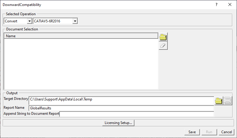
Saving files in lower version

Many a times there will be a requirement of saving files in lower version as the person to whom it is shared may not be having the same release.

For this, the downward compatibility option is used.

Select the desired option and save.

Click on Tools ➜ Downward Compatibility ➜ Save

Save options in CATIA V5-5

Customizing CATIA CATSettings

Every organization has its own standards and requirements when it comes to designing in CATIA. To adhere to these standards and requirements, some changes need to be made in the software application settings. In this article, setting up of global environment using customization setting from single source is explained in detail.

Introduction:

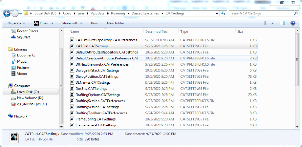
  • From selecting license while opening CATIA V5 to modifying shortcut keys for commands, all settings done in CATIA are saved as CATSettings. CATSettings files are created once a user does some customization. A single CATSettings file may contain multiple attribute values.
  • To make sure that users meet key company design practices and industry standards, CATSettings need to be administered. For the same reason, many OEMs create their own environment in CATIA and ask vendors to use the same.
  • CATSettings created by users are stored in CATUserSettingPath.
  • CATSettings created by administrators are stored in CATReferenceSettingPath in environment file.

Customizing CATIA CATSettings-1
There are many advantages of customizing CATIA settings which are listed below:

  1. It will lead to standardization of CAT Settings.
  2. Unnecessary start up settings and configurations are avoided.
  3. Default paths can be set which eliminates searching time.
  4. Custom Environment is created.
  5. Custom start parts and drafting standards are created.
  6. Best practices are followed by users.

The following steps are performed to set up CATIA V5 variables:

  1. Create a folder in the name of EDST_CATIA_Environment on network drive.
  2. Create two more folders in the name of say CAT_COLLECTION_STANDARD and CAT_Refrence_settings_path in EDST_CATIA_Environment folder.
  3. Click on CAT_Refrence_settings_path folder and copy the path from the Address
  4. Environment Editor can be opened by clicking Start > All Programs > CATIA > Tools > Environment Editor V5 R29 (the release issued from the user company).
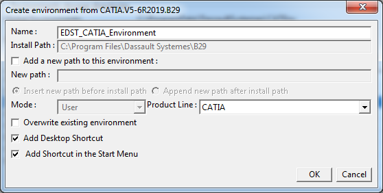
  5. For setting new environment, click Environment New From and rename it as EDST_CATIA_Environment and click OK.
    Customizing CATIA CATSettings-2
  6. Environment is created and desktop icon is also generated for the same.

  7. The new environment file location is saved at the location:

    C:\User\hostname\AppData\Roaming\DassaultSystemes\CATEnv

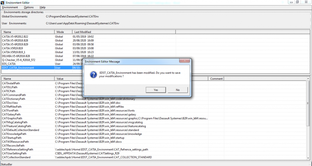
  8. Select Environment (EDST_CATIA_Environment), click on CAT_Reference_settings_path and right click on variable.

    Click on Edit Variable. Now paste the path copied earlier.
    Customizing CATIA CATSettings-3

    Similarly, copy and paste the same path for CAT_COLLECTION_STANDARD.

  9. Now save the modifications and exit the workbench.

    Customizing CATIA CATSettings-4

    Now, the modified CATIA Environment is created successfully.

  10. Copy Environment file from C:\User\hostname\AppData\Roaming\DassaultSystemes\CATEnv and paste to the network drive. EDST_CATIA_Environment folder will be created.

The following are the steps to launch CATIA in Admin mode:

  1. Copy and paste the CATIA icon (in this document EDS_CATIA_Environment) on desktop.
  2. Rename EDS_CATIA_Environment to EDS_CATIA_Environment-ADMIN (only for reference)
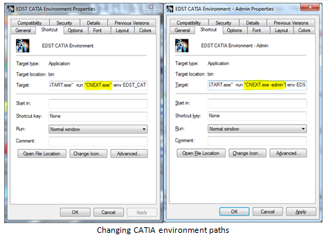
  3. Right click on EDS_CATIA­_Environment-ADMIN ➜ Properties
  4. Search for CNEXT in target tab and change exe to CNEXT–Admin.exe
  5. Change directory of Environment from “C:\Users\user\AppData\Roaming\DassaultSystemes\CATEnv“–nowindow to EDST_CATIA_Environment -direnv “Network Location“–nowindow for both EDS_CATIA_Environment and EDS_CATIA_Environment –ADMIN icons.
    Changing CATIA environment paths

    Customizing-6

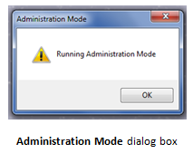
    Now click EDS_CATIA_Environment-ADMIN and CATIA will be opened in Administration Mode.

    Customizing-7

Steps followed to modify System settings:

  1. Go to ToolsOptions
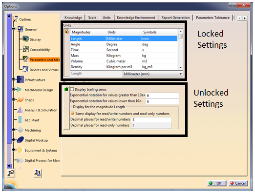
  2. Settings with a lock sign will appear
  3. Modify the required settings
  4. Click on the lock sign to lock the settings

    Customizing-8

Reset and Dump settings:

  1. This is used to reset CATSettings to default value. User can reset the values which are changed to default. It can be changed for tab, workbench, selected solution and for all tab pages.

    Customizing-9

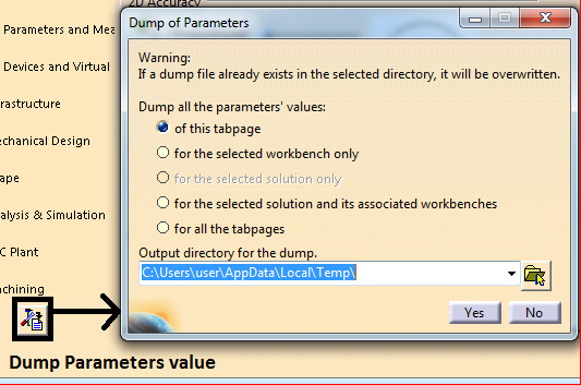
  2. To view values of given settings, comparing settings between different releases and viewing each attribute of settings in detail, dump settings are created. This setting is used to create CATVBS files of settings.

    Customizing CATIA CATSettings-10

How to Solve CATIA V5 R29 GA Installation Error

When the setup application is launched, Some times CATIA V5-6R2019 GA installation crashes out immediately. This is due to the bug reported in the original installation launcher. In this blog, we learn how to resolve this error while installing CATIA V5 R29 GA.

  1. What is the CATIA V5 R29 GA installation error?
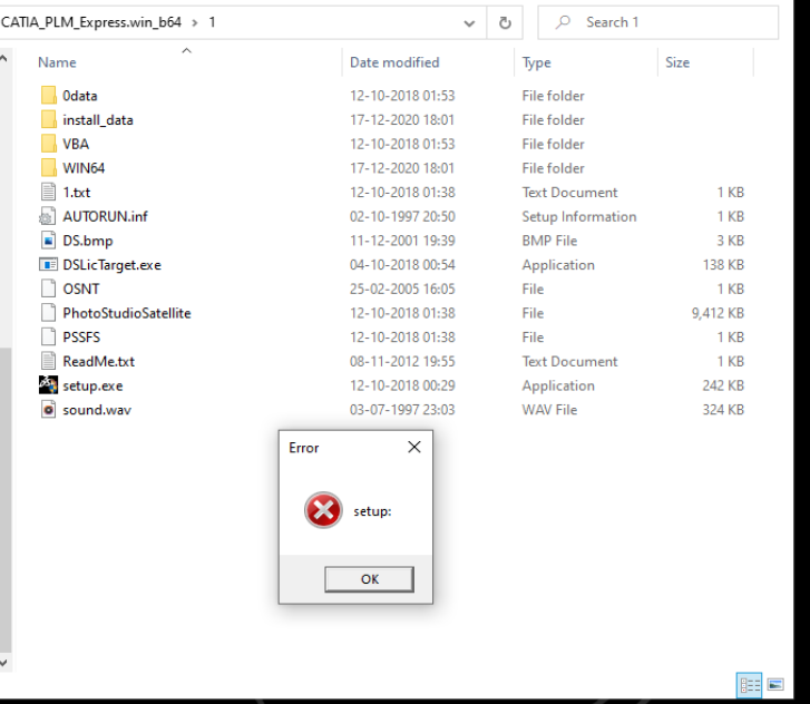
  2. While installing CATIA V5 R29 PLM Express or Legacy configurations, CATIA displays the following error.

    How to Solve CATIA V5 R29 GA Installation Error-1
    This error occurs due to the redistributable packages installed in Windows 10.

  1. What are the steps to resolve this error?
    • Download any CATIA V5 R29 Service Pack (1 to 5) from DS support portal.
    • Extract the ZIP file.
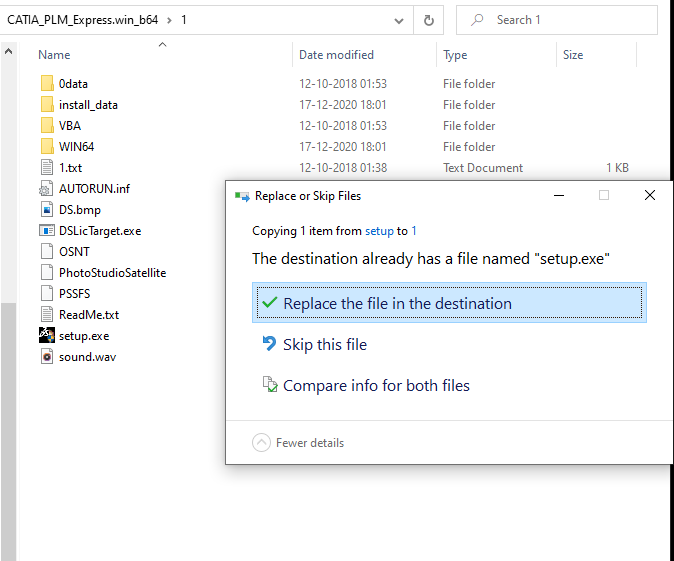
    • Copy exe file from location:

    V5-6R2019.SP1.SPK.win_b64.1-1\SPK.win_b64\1\FIXGA

    • Replace existing exe file in GA folder with the downloaded setup.exe from Service Pack.
      How to Solve CATIA V5 R29 GA Installation Error-2


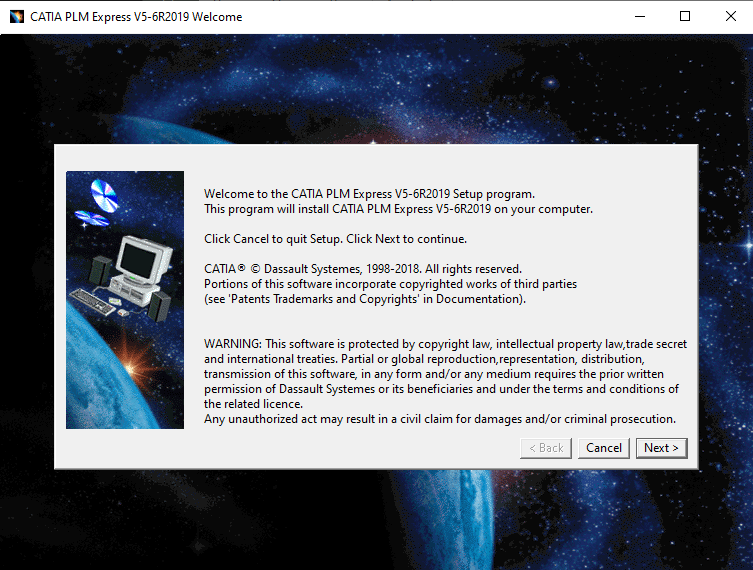
    • After replacing exe file, CATIA V5 R29 installation starts without any error.
    • How to Solve CATIA V5 R29 GA Installation Error-3

    By downloading and replacing setup.exe file in CATIA V5 GA folder, CATIA V5 R29 can be installed without any error.

Subscribe to our newsletter

Get all the latest information on Events, Sales and Offers.