Enforcing Contact Constraints Using Penalty Contact Method in Abaqus

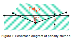
There are two primary methods through which normal direction contact constraints can be enforced in Abaqus/Standard: the traditional direct Lagrange multiplier method and a penalty-based method. The fundamental difference between the two methods is that the Lagrange multiplier method exactly enforces the contact constraint by adding degrees-of-freedom to the problem while the penalty method approximately enforces the contact constraint through the use of “springs” without adding degrees-of-freedom. The penalty method is depicted schematically in Figure 1. The lower surface is the main node and the upper surface is the secondary node. While the overclosure has been exaggerated, it is clear that the spring of stiffness kp resists the penetration of the secondary node into the main surface.
Enforcing Contact Constraints Using Penalty Contact Method in Abaqus-5

A large class of problems exists where the extra accuracy that is possible with the Lagrange multiplier method is not consistent with the approximations that are made (i.e., coarse meshes). Often times in these problems, adequately capturing load transfer through the contacting interface is more important than precise enforcement of the zero-penetration condition. The penalty method is attractive in such applications because it is usually possible to trade off some small amount of penetration for improved convergence rates.

The penalty method implementation in Abaqus attempts to choose a reasonable penalty stiffness based on the underlying element stiffness. If the default penalty stiffness is not suitable, options to scale the penalty stiffness are available. It is also possible to prescribe the penalty stiffness directly. If the scaled or user-prescribed penalty stiffness becomes very large, Abaqus automatically invokes special logic that minimizes the possibility of ill-conditioning. Advantages and disadvantages of each method are listed in Table 1.

Table 1: Direct Lagrange multiplier vs. penalty method
Direct Lagrange multiplier contact Penalty contact
Advantages Disadvantages Advantages Disadvantages

· Exact constraint enforcement (zero penetration)

· Easy to recover contact forces

·No need to define contact stiffness

· Larger system of equations

· Difficult to treat over constraints

· Sensitive to chattering

· Number of equations does not increase

· Easier to treat over constraints

· Approximate constraint enforcement (finite amount of penetration)

· Difficult to choose proper penalty stiffness


Linear and Non-linear Penalty Stiffness

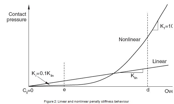
With the non-linear penalty stiffness approach, the penalty stiffness has constant initial and final values; these values serve as bounds for an intermediate overclosure regime in which the stiffness varies quadratically. A schematic comparison of the pressure-overclosure relationships for the linear and nonlinear penalty methods is given in Figure 2:
Enforcing Contact Constraints Using Penalty Contact Method in Abaqus-5

The various parameters used for defining the non-linear pressure-overclosure relationship are given below:

  • Klin–  Linear stiffness used for linear penalty contact. The default value is 10 times a representative underlying element stiffness.
  • C0–  Clearance at which contact pressure is zero. The default value is zero.
  • Ki–  Initial stiffness. The default value is 1/10 of the linear penalty stiffness.
  • Kf–  Final stiffness. The default value is 10 times the linear penalty stiffness.
  • d  –  Upper quadratic limit. The default value is 3% of the characteristic length computed by Abaqus/Standard to represent a typical facet size.
  • e  –  Lower quadratic limit. The default value is 1% of the characteristic length computed by Abaqus/Standard to represent a typical facet size.
  • er= e/d  –  Lower quadratic limit ratio. From the default values of parameters d and e, the default value for er is 0.3333.

The default values for these parameters are based on the characteristics of the underlying elements of the secondary surface.  For two elements with dissimilar materials in contact with each other, the contact penalty stiffness value chosen will be based on the material stiffness of the softer material. User control for changing the default values is provided. The nonlinear penalty method has the following characteristics:

  • A relatively low penalty stiffness is used while the contact pressure is small. This serves to reduce the severity of the discontinuity in contact stiffness when the contact status changes.
  • The smooth increase of the penalty stiffness with overclosure helps avoid inaccuracies associated with significant penetrations without introducing additional discontinuities.

The low initial penalty stiffness typically results in better convergence for problems that are prone to chattering with linear penalty contact, and the higher final stiffness keeps the overclosure at an acceptable level for problems with high contact pressure. Nonlinear penalty contact tends to reduce the number of severe discontinuity iterations due to a smaller initial stiffness; however, it may increase the number of equilibrium iterations due to the nonlinear pressure-overclosure behaviour. Hence, it cannot be guaranteed that nonlinear penalty contact will result in a reduction of the total iteration count compared to linear penalty contact.

As discussed above, Abaqus attempts to choose reasonable penalty stiffness values based on the underlying element stiffness. Experience has shown that for stiff or blocky problems the default penalty stiffnesses chosen by Abaqus produce results that are comparable in accuracy to results produced using the direct Lagrange multiplier method but usually at less expense in terms of memory and CPU time. Experience has also shown that for bending-dominated problems the default linear penalty stiffness can often be scaled back without any significant loss of accuracy. Furthermore, scaling back the penalty stiffness for bending-dominated problems has been seen to sometimes dramatically increase the convergence rate. These experiences are demonstrated by the following examples.

Example: Hertz contact

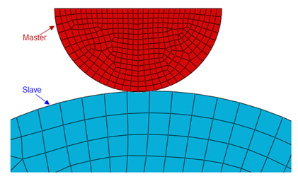
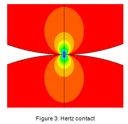
This example consists of two elastic cylinders in contact as depicted in Figure 3. The node-to-surface formulation with matching meshes was used. Cases were run using the direct Lagrange multiplier method, the linear penalty method with default stiffness, and the linear penalty method with default stiffness scaled back by two orders of magnitude. Results from the three cases are presented below in Table 2.

As expected, the direct Lagrange multiplier case produces zero penetration while the cases that use the penalty method produce finite penetrations. In this example, scaling down the penalty stiffness by a factor of 100 results in a 55x increase in the penetration. It can be seen that for this example the default penalty stiffness predicts a peak stress that differs by only 1.5% from the peak stress that is computed using the direct Lagrange multiplier method. If the penalty stiffness is scaled back by a factor of 100 then the predicted peak stress decreases considerably and differs by 47% from the peak stress that is computed using the direct Lagrange multiplier method. The significant decrease in peak stress is due to the combination of displacement controlled loading and the compliance at the contact interface with the penalty method.
Enforcing Contact Constraints Using Penalty Contact Method in Abaqus-5

Table 2: Hertz contact results

Penetration Peak Stress
Direct Lagrange 0 1.201E5
Linear Penalty, default stiffness 4.482E-6 1.183E5
Scaled Linear Penalty, Sf = 0.01: 2.492E-4 6.334E4


Example: Bending-dominated contact

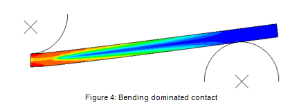
This example consists of a three-point bending test of an elastic-plastic beam as depicted in Figure 4. The node-to-surface formulation and half symmetry have been used. Cases were run using the direct Lagrange multiplier method, the linear penalty method with default stiffness, and the linear penalty method with default stiffness scaled back by two orders of magnitude. Results from the three cases are presented below in Table 3.

As expected, the direct Lagrange multiplier case again produces zero penetration while the cases that use the penalty method produce finite penetrations. In this example however, it can be seen that both cases that use the penalty method predict a peak stress that is practically identical to the peak stress computed using the direct Lagrange multiplier method. The behaviour that is seen in this example where a relatively small penalty stiffness produces quite accurate stress results generalizes to a very large class of bending-dominated problems. It can also be seen that in this example the penalty method produces a more economical solution as measured by iteration counts that decrease as much as 14%.
Enforcing Contact Constraints Using Penalty Contact Method in Abaqus-5

Table 3: Bending dominated contact results

Penetration Stress Iterations
Direct Lagrange 0 2.416E4 130
Linear Penalty, default stiffness 1.004E-7 2.416E4 117
Scaled Linear Penalty, Sf = 0.01 1.015E-5 2.416E4 112


Usage

The penalty method is applicable to all contact formulations. The linear penalty method is used by default for the finite sliding surface-to-surface formulation (including general contact) and for three-dimensional self-contact; the direct Lagrange multiplier method remains the default constraint enforcement method in some cases. In order to activate the penalty method use the options listed below.

Abaqus/CAE

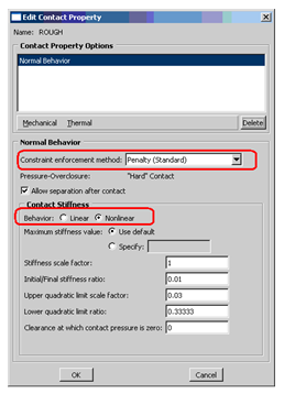
In the Interaction module, open the Interaction Property Manager by selecting Interaction  Property  Manager. Select the appropriate interaction and click Edit to receive the Edit Contact Property dialog. Select Mechanical  Normal Behaviour → constraint enforcement method: Penalty (Standard) → behaviour: [Linear | Nonlinear] as shown below:
Enforcing Contact Constraints Using Penalty Contact Method in Abaqus-5

Input file

The penalty method is selected with the following keyword options:
*SURFACE BEHAVIOR, PENALTY = [ LINEAR | NONLINEAR ]
The data lines can be used to modify the default settings for either the linear or nonlinear approaches.

How to Enforce Contact Constraints using Augmented Lagrangian Method in Abaqus/Standard?

There are three methods of contact constraint enforcement that are available in Abaqus/Standard:

  • The direct Lagrange multiplier method,
  • The augmented Lagrangian method, and
  • The penalty method

In this blog, the differences between direct and augmented Lagrangian methods are focussed.

Within the context of the classical “hard” contact problem, the direct and augmented Lagrangian methods differ as follows:

How to Enforce Contact Constraints using Augmented Lagrangian Method in Abaqus-Standard-1

Direct method:

  • Enforces the contact constraint exactly so that no penetration of the slave nodes into the master surface is allowed.

Augmented Lagrangian method:

  • Enforces the contact constraint approximately using the penalty method. The penalty stiffness is scalable.
  • Non-zero penetration of the slave nodes into the master surface is allowed and penetration tolerance is adjustable.
  • Once solution convergence is obtained, if a slave node penetrates the master surface by more than the relative penetration tolerance of 0.1% (default setting) of the characteristic interface length, the contact pressure is “augmented”. Iterations continue again until convergence. The solution is accepted when the penetration tolerance is accepted.
  • Can sometimes be more expensive than the Lagrange multiplier approach as a result of the augmentation scheme and additional iterations.
  • How to Enforce Contact Constraints using Augmented Lagrangian Method in Abaqus-Standard-1

In general, the approximate nature of the augmented Lagrangian contact constraint can simplify the resolution of difficult contact problems and sometimes allow a solution to be found when the exact, Lagrange multiplier constraint is too restrictive. With the ability to scale the penalty stiffness and the penetration tolerance, the contact constraint can be relaxed to facilitate convergence; however this must be done with caution and the results must be carefully checked for excessive penetration of the contact surfaces. More specific situations where this approach can help include:

  1. Very different mesh densities on contact pair surfaces
  2. Non-uniform contact pressure distributions are more likely to occur when very different mesh densities are used on the two deformable surfaces making up a contact pair. If the Lagrange multiplier method is used, the non-uniformity can be particularly pronounced, and oscillations and spikes in the contact pressure may occur, when both surfaces are modelled with second-order elements (including modified, second-order tetrahedral elements). Smoother contact pressures may be obtained for surfaces modelled with second-order tetrahedral elements by using the augmented Lagrangian approach.

    How to Enforce Contact Constraints using Augmented Lagrangian Method in Abaqus-Standard-1
  1. Over-constraint problems
  2. An over-constraint occurs when a contact constraint on the displacements, temperatures, electrical potentials or pore fluid pressure at a slave node conflicts with a prescribed boundary condition or other kinematic constraint on that degree of freedom at the node. Specified boundary conditions on the master surface nodes typically do not cause over-constraints. Specified boundary conditions on slave nodes may create an over-constraint.

    Over-constraints can be avoided only by changing the contact definition or the boundary conditions. Over-constraint problems may also be alleviated by using the augmented Lagrangian contact constraint enforcement method. While this may help in certain difficult situations, it is generally preferable to remove the source of the over-constraint.

How to model a structure undergoing global instability in Abaqus?

A nonlinear static problem can be unstable as a result of global buckling or material softening. If the load-displacement response of the model seems to be reaching a load maximum and there is the possibility of global instability or negative stiffness, two approaches to solving the problem can be used — static or dynamic analysis.

  • If the structure is reaching a buckling load in a static analysis, perform a Riks analysis.
    The Riks method assumes that the global instability can be controlled by modification of the applied loads. This means the loss in stability cannot be too severe; that is, there cannot be a sharp bifurcation in the load-displacement curve. Therefore, structures such as flat sheets, cylinders, and spheres that have a sudden significant loss of stiffness after buckling must have some imperfection built into the original geometry.

    This can be done by using the *IMPERFECTION option to modify the original geometry by adding imperfections. The best approach is to use experimentally determined imperfections; however, since these measurements may not be available, the *IMPERFECTION option can use combinations of the eigen modes from a previous buckling analysis as the imperfections to the original geometry.

    If the Riks method fails to converge near a limit or bifurcation point (buckling load), the problem may be that the loss in stiffness is too severe. Instability problems that exhibit a sharp transition often require a limit on the maximum incremental arc length to get past the transition point or to have larger imperfections built into the geometry.

  • If a dynamic analysis is desired, Abaqus/Explicit should be considered as the most robust approach, particularly in the presence material failure, extreme deformation, or rapid changes in contact state. If the loss in stability is not too severe, or only the load maximum is to be computed rather than a fully collapsed configuration, then a dynamic analysis in Abaqus/Standard may be completed with less run time. Choose the APPLICATION parameter on *DYNAMIC to control the amount numerical damping that is applied to the integration operator. If a dynamic analysis is used in Abaqus/Explicit, the structure will vibrate once it has passed the instability and you must decide how to damp the vibrations if a quasi-static solution is required.

Global instabilities can also be stabilized in a static analysis with viscous forces. Although not intended as a primary solution technique for global instabilities, automatic stabilization can be used in the static, coupled temperature-displacement, soils and quasi-static procedures. Automatic stabilization will add viscous damping to the structure, which may allow the solution to go beyond the instability point.

Discrete dashpots can also be used to stabilize a problem of this type.

With either technique, the energy dissipated by the artificial viscous forces (output variable ALLVD for discrete dashpots or ALLSD for automatic stabilization) should remain small compared to the total internal energy (output variable ALLIE) in the problem. The nodal viscous forces should also be small when compared with typical forces in the problem (use nodal output variable VF).


How to Design Complex Aero Parts using the 3DEXPERIENCE Platform?

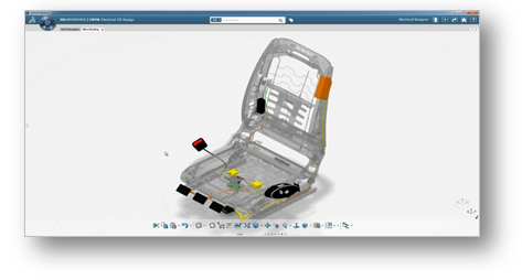
Designing aircrafts is becoming an increasingly complex task these days. As it becomes increasingly sophisticated, the wiring needed to power and control the electrical systems are also becoming complex.

Large OEMs and companies are dependent on electrical CAD systems which will enable them to execute the electrical diagram which will help in 3D Mock-Up and manufacturing preparation. This will help these OEMs and companies to lower production costs and also to reach the market faster than before.

What are the typical challenges with respect to Wire Harness?

  • Multi applications and different data sources
  • Time consuming, repetitive and error prone creation of electrical system
  • Lack of 3D integration with electrical system schematics which will lead to difficulty in understanding the overall design quality
  • No associativity between 3D wire harness design and its manufacturing

How to Design Complex Aero Parts using the 3DEXPERIENCE Platform1

Due to the complexity and stringent safety regulations in the Aerospace sector, virtual testing and validation plays a significant part in design and manufacturing.

How 3DEXPERIENCE addresses these challenges?

Large OEMs and companies have adopted Dassault Systèmes’ 3DEXPERIENCE platform which accelerates the process from design to manufacturing with compliance to required standards.

The 3DEXPERIENCE platform provides end-to-end electrical development environment from schematics through 3D design up to manufacturing.

Some of the solutions which the 3DEXPERIENCE platform offers with respect to Wire Harness are described below:

CATIA 3DEXPERIENCE – 3D Wire Harness Design

  • Shared electrical systems data model which enables schematic to 3D Design synchronization
  • Best-in-class 3D wire harness design solution
  • In-context wire harness modelling and simulation
  • How to Design Complex Aero Parts using the 3DEXPERIENCE Platform1

CATIA 3DEXPERIENCE – Harness Manufacturing Preparation

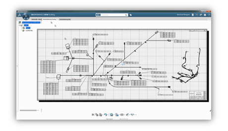
  • World class wire harness layout solution
  • Automatic generation of full-scale drawings for form-board manufacturing
    How to Design Complex Aero Parts using the 3DEXPERIENCE Platform1
  • Synchronization of flattened harness and automatic drawing updates

Large aerospace OEMs and suppliers have reaped multiple benefits by adopting Dassault Systèmes’ 3DEXPERIENCE platform. Some of these are mentioned below:

  • Integrated process coverage to reduce cycle time from design to manufacturing
  • Detect issues in the early phase of design by validating virtually and avoid expensive errors in manufacturing
  • Automatic propagation of modification from design to documentation
  • Quick electrical space reservation within the product to avoid physical prototypes

Thus, the 3DEXPERIENCE platform and its various applications help OEMs as well as suppliers to design and manufacture complex parts rapidly and with accurate precision while adhering to safety standards.

Abaqus Discrete Element Method

The computation of effect and motion of a large group spherical particles, where the particles interact with one another and with other surfaces/flow is known as discrete element method (DEM). Granular particles can be simulated in Abaqus using DEM in Abaqus/Explicit Analysis. Abaqus also has another technique to model particles and the technique is known as Smoothed Particle Hydrodynamics (SPH). The major difference between DEM and SPH is that in SPH technique, the particles collectively have continuum behaviour whereas in the DEM technique, the particles cannot undergo a large complex deformation by themselves. Also, DEM technique is a much simpler method.

DEM particles are rigid single-node elements with a certain radius. Particle nodes have degrees of freedom for translational motion and rotation, so considering friction, the latter can significantly affect behaviour, through general contact method. For DEM particles, a contact penalty process is used, which introduces flexibility into the particle system. This correspondence can be used to model the macroscopic stiffness of the filled granular material. Alternatively, the Hertz contact method can be used for particle interaction.

DEM debris may be initialised in the beginning of the analysis, or may be generated all through the analysis. When generated, a random radius, primarily based totally on a user-specified chance density function, may be assigned to every particle. To analyse more complicated shapes in place of easy spheres, more than one DEM debris may be mixed in a cluster the usage of MPC constraints. Clusters aren’t well suited with the particle generator.

Each DEM particle is modelled with a single node element type of PD3D.  The PD3D element type have displacement and rotational degrees of freedom. When friction is considered for a study, the rotational degree of freedom of the discrete element particles has a considerable effect on the contact interactions.

Interaction between Particles


DISCRETE ELEMENT METHOD1

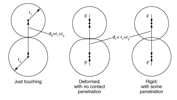
Let us consider three instances of particles in contact as shown in the above figure. The 3 instances display undeformed spheres simply touching, deformed spheres driven closer to each other with contact strictly enforced, and rigid spheres penetrating each other. The distance among the facilities of the spheres is the identical for the middle and right instance as shown in figure above. The middle instance of deformed spheres with no penetration is of physical behaviour. The right instance of rigid spheres penetrating each other is a typical DEM approximation.

If the variable δ is defined as:

δ=r1+r2−d,

where r1 and r2 are the radii of the two spheres and d is the distance between the sphere centres,  when the undeformed spheres are just touching then δ=0  and  if the distance between the sphere centres is less than the combined radii the δ>0 . For the DEM approximation, δ corresponds to the maximum penetration distance between the particles. If the contact stiffness is tuned i.e., contact force v/s penetration, then the accuracy of some DEM applications can be improved. Also, tuning helps to replicate the Hertz contact solution for DEM particles.

Why Use DEM?

  • Each DEM particle has individual rotational, positional, radial and momentum vectors that can be easily calculated.
  • Simulating DEM method is quite simpler than SPH method and consists of initialisation, time stepping and post processing.
  • DEM can be ideally used for modelling granular matter, powders, rock masses, particle packing, particle flow, particle fluid interaction, colloids etc.

Applications of DEM

  • Mixing of Chemicals
  • Pharmaceuticals
  • Powder Metallurgy
  • Ceramics
  • Food industry
  • Agriculture
  • Geophysics/Seismology
  • Rock fracture
  • Soil Mechanics
  • Ice blocks floating into bridge supports
  • Mining
  • Mineral Processing
  • Oil and Gas


DISCRETE ELEMENT METHOD1


DISCRETE ELEMENT METHOD1

Advantages of DEM  

  • DEM is used to study micromechanical level of analysis describing every single position, rotation and velocity for every single particle.
  • Accurately model granular and discontinuous materials using DEM to validate models virtually thereby saving a lot of costs that would other incur for the physical testing.
  • DEM can be coupled with CFD and FEM to model progressive fracture.

How to Execute a Job without opening Abaqus using Command Prompt?

A job can be run from the command prompt without opening Abaqus CAE as long as the job is set up and already saved. Command prompt is used to submit the analysis. This will be helpful if the pre-processing stage of the model is completed. Pre-processing can be done in any of the pre-processors including ABAQUS, but to run the analysis using ABAQUS, the file format must be converted to input file (.inp). The main reason behind this is to run several jobs simultaneously based on availability of CPU storage and tokens. Submitting the job through CAE is also available to run the analysis but this method will be helpful for user when he can access the job submission by using the command window.

Following are the steps to be followed to run the analysis using command prompt:

  1. Go to the folder in which input file (.inp) is located. Input file is the one which contains all the pre-processed data of the model.
  2. Select the path of the folder, type cmd in the place of path and click Enter. With this, Command prompt will be opened and will step in to the folder where input file is located.

    Execute a Job without opening ABAQUS -1
  1. Now type the command to run the job abaqus j=<type input file name> cpus=<no. of CPU> and click Enter. The analysis will begin and different files are generated in the folder during the analysis.

    Execute a Job without opening ABAQUS -1
  1. The results can be visualized with output database file (.odb) once the analysis is completed.
  2. If the job already exists in the selected folder while executing the job in command prompt, the job can be overwritten. This can be done by giving the input as “y” and click Enter.


    Execute a Job without opening ABAQUS -1
  1. If the job needs to be terminated, the command abaqus terminate job=<type input file name> can be given as input. With this above command, the analysis can be terminated.


    Execute a Job without opening ABAQUS -1

This is the step-by-step process to execute analysis by using the command prompt. This method is helpful for running multiple jobs of pre-processed model.

Subscribe to our newsletter

Get all the latest information on Events, Sales and Offers.