DIGITAL DYNAMISM – THE NEED OF THE HOUR

Olympics Motto “Faster, Higher, Stronger – Together” inspires me while writing this article on Digital Dynamism. Olympics is an event that symbolizes unity and exuberance of the human spirit.

This is the same Olympic spirit which is needed for the organizations to adapt digital technologies and transform the consumer experiences with sustainable innovations in harmony with nature.

The term Faster would refer to agility of the organizations to improve and develop continuously. This could be improving faster time to market, scaling production capabilities, expanding the businesses into new horizons etc.

Higher would refer to organization’s vision for ethical business practices and quality standards and productivity with a process-centric approach involving rich data collection, data-driven customer insights and business intelligence.

Stronger represents organization’s performance through market and talent access and effective resource management. It can also connect with company’s IT infrastructure, data security and IP protection.

The term Together brings in the value of greater collaboration across the organization as well as extended organization involving suppliers, partners, consultants and importantly the consumers.

Digital Dynamism carries the Olympic spirit in achieving unparalleled excellence focusing on sustainable innovations imbibing digital cultureActors using the digital experience platforms can access latest and up-to-date information/ data on any device, anywhere and at any time. Key enablers like cloud technologies, industrial IoT, artificial intelligence fueled automations, machine learning and data analytics would play a pivotal role in bringing digital dynamism to the organizations.

In the manufacturing arena, digital dynamism can be perceived through IIoT and cyber physical systems’ enabled shop floors gathering critical data on the product, process and resources (machines, equipment and operators) leading to predictive analytics and maintenance. OEE (Overall Equipment Effectiveness) can be easily tracked and monitored for higher manufacturing productivity.

Finally, digitally skilled workforce can bring in the dynamic transformation in every industry segment improving the product, nature and life.

Dassault Systèmes’ 3DEXPERIENCE Platform is a digital experience platform for the organizations which helps in reimagining the products and experiences, and rethink business processes and operations. It connects people, ideas, data and solutions in a single collaborative environment empowering business – from start-ups to large enterprises, to innovate, produce and trade in entirely new ways. 

The platform acts as a single version of truth to anchor outcome-based processes and capture all activities in one place. It securely connects individuals, teams, departments and external collaborators working together to transform ideas into innovative products, services and experiences.

For more details on digital dynamism and digital experience platforms, please write to info@edstechnologies.com or marketing@edstechnologies.com



Reinforced Cement Concrete (RCC) Structure under Compression Load Conditions: ABAQUS/SIMULIA

Introduction

The RCC structure displayed below is subjected to displacement under static conditions in ABAQUS GUI. The basic purpose of using RCC is to absorb stresses (specifically tensile stresses) that arise in the structure. From a structural engineering point of view, concrete is weak in tension, and therefore it is reinforced accordingly with suitable material. To overcome the crack development due to variation in temperature and stresses (shrinkage) also, reinforcement is used. RCC also enhances the strength of concrete sections.

Geometry and meshing

To begin with, three parts were created:

  1. The first part is a solid homogenous rectangular part as shown in the picture. It was specified as concrete.
  2. Internally stirrups and wires were created, both of them aligned in parallel within the structure.

For concrete, C3D8R (An 8-node linear brick, reduced integration, hourglass control) was assigned. For internal wires and stirrups, T3D2 (A 2-node linear 3-D truss) were used.

f1

Figure 1: 3D model of RCC with wire and stirrups reinforcement

Material

Under material definition, linear elastic property was assigned. Steel properties were used for stirrups and wire reinforcements. The outer body was considered as a concrete body, with solid homogenous sections. The reinforced body is considered as a truss section.

Loading and Boundary Conditions

The simulation was conducted under static conditions. During the first step, the RCC Beam remained at static conditions. Both sections internally and externally were under static conditions. During the second step, a displacement of 50 mm was given to see the deformation. Also, two distinctive boundary conditions were employed: primary one was given as pinned (U1–U2–U3=0) to fix the translational and rotational motion of the structure, while the secondary boundary condition was defined as a displacement of 50 mm in Y – directions as shown in Figure 2. The approach was to generate axial deformation. The analyses were performed using Abaqus/CAE.

f2

Figure 2: Boundary conditions assigned to the RCC Structure

Interactions

Embedded interactions were defined between internal and external parts. 3D Solid – in – Solid principle was used while implementing the interactions. This technique helps us specify that an element or group of elements is embedded in “host” elements. Abaqus searches for the geometric relationships between nodes of the embedded elements and the host elements. Therefore, stirrups and wires were embedded in the concrete structure. Default fractional exterior tolerance value of 0.025 was specified. Figure 3 displayed below was based on the embedded interactions; the red area was considered as embedded while the outer area was considered as a host.

f3

Figure 3: Embedded interactions defined between external and internal parts

Results

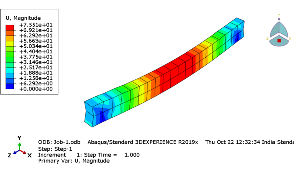
As expected, non-uniform displacement arises in the center of the structure.  Higher stresses experienced throughout the structure are as shown in Figure 1. While plotting stress – strain graph along the length of the RCC, higher compression stresses were seen in comparison to tensile stresses.

f4

Figure 4: Stresses and displacement arisen in the RCC Structure under linear elastic conditions

f5

f6

Conclusions

To conclude, ABAQUS is a well-suited integrated package for contact analysis. Modelling and simulation of RCC was presented in elementary way regardless of complex contact nonlinearity. Axial stress – strain displacement relationship under embedded interactions were studied in this case. In a similar way, more complex relationship such as stirrups and wire thickness influence, orientation of the wires or even more complex loading conditions can be investigated.

EDS Technologies helps customers to adopt right simulation solutions to tackle complex real-world problems. We also provide comprehensive training on SIMULIA suite of solutions for our customers. Contact us to know more about SIMULIA/Abaqus and how it can be effectively used to add value in your organization.

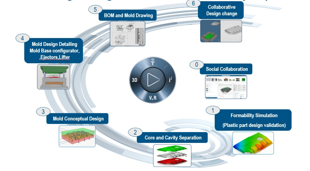
Integrate Mold and Tooling with 3DEXPERIENCE Platform for first-time-right design

Major challenge for tool makers is the quick turn around and reduce design to manufacturing cycle time as required in every industry. Every manufacturer’s goal is constant innovation to manufacture products with ever improving quality at the right cost. Maximizing efficiency and reliability of tooling regardless of human and resource related contingencies will accelerate the product delivery.

Tool makers work as a collaborative team and the latest product data is misplaced with the collect, exchange, translate and duplicate of data. Tool makers also collaborate with designers. There are multiple iterations of product data from designer to toolmaker and vice versa. With numerous collaborators, there is bound to be numerous iterations due to defects from manufacturability issues. It is necessary to have various iterations to reach at a refined final product but leads to delays in the tooling delivery.

Other challenges faced by tool makers are:

  • Collaborators use different software for design, simulation and manufacturing leading to high data translation cost.
  • Significant amount of time is spent in integrating product design changes due to excessive engineering and poor standardization.

Integrate Mold and Tooling with 3DEXPERIENCE Platform for first-time-right design

mold

With CATIA Mold and Tooling solution, companies are able to create first-time-right collision-free tool paths  through the fully integrated and collaborative 3DEXPERIENCE platform. Easy access to designs to create the appropriate tooling in a single environment is helpful to interact with collaborators, eliminating the need for data translation and to easily freeze product design.

Features of CATIA Mold and Tooling solution

  • Powerful, flexible, and highly customizable experience to address the mold making requirements and challenges
  • Increased design productivity, standardize tooling design practices, automate design tasks and assist decision-making from simple to complex projects
  • Added value to manufacturing companies to produce high quality products
  • Avoid modification cycles and attached costs with design right the first time
  • Consistently deliver high quality tooling
  • Minimize risk of critical situations
  • Increase competitive edge

3 Key Benefits of CATIA Mold and Tooling solution

  1. Increase productivity and reduce cycle time:
    1. Dedicated capabilities addressing toolmakers’ specific needs
    2. Ease to capture, reuse and grow company resource
  2. Promote standardization and ensure lifecycle integrity:
    1. Single software platform for integrated tooling design and manufacturing
    2. Full 3D visual simulation for reference throughout the process
  3. Enhance quality and bolster innovation:
    1. Automate tasks and assist user decision and enable collaborative engineering

Contact us to know more about how CATIA 3DEXPERIENCE can aid your team for first-time-right design.

Realistic Simulation Supports Expansion of the London Underground

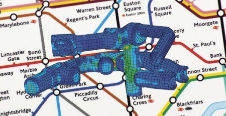
Dubbed “one of the most complex tunneling projects in the U.K.,” the Bond Street Station Upgrade (BSSU) project is being carried out to satisfy growing traffic demands within London’s busiest shopping district, the West End.

Upon its completion, Bond Street Station’s daily passenger numbers are expected to rise from 155,000 to 225,000.

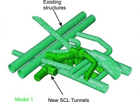
A project this complex in nature has to consider the existing tunnel infrastructure, as well as the stress and strains imposed by the surrounding soil layers for the development of new tunnels.

Dr. Sauer and Partners was contracted to provide such tunneling expertise. The company took on responsibility for preliminary-to-detailed design and

Using FEA simulation, they were able to virtually test the ground through which the tunnels are being dug alongside the existing tunnel structures.

Model1.000

This realistic assessment enabled them to improve upon the preliminary design, as well as bring greater confidence to the overall approval process.

To learn more, read the case study, “Tunnel Vision” to see how realistic simulation plays an important role in tunnel excavation.

We also encourage you to download the whitepaper by Ali Nasekhian, Sr. Tunnel/Geotechnical engineer at Dr. Sauer and Partners, which highlights the merits and shortcomings of large 3D models in tunneling.

Subscribe to our newsletter

Get all the latest information on Events, Sales and Offers.