Customizing CATIA CATSettings

Every organization has its own standards and requirements when it comes to designing in CATIA. To adhere to these standards and requirements, some changes need to be made in the software application settings. In this article, setting up of global environment using customization setting from single source is explained in detail.

Introduction:

  • From selecting license while opening CATIA V5 to modifying shortcut keys for commands, all settings done in CATIA are saved as CATSettings. CATSettings files are created once a user does some customization. A single CATSettings file may contain multiple attribute values.
  • To make sure that users meet key company design practices and industry standards, CATSettings need to be administered. For the same reason, many OEMs create their own environment in CATIA and ask vendors to use the same.
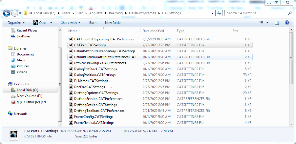
  • CATSettings created by users are stored in CATUserSettingPath.
  • CATSettings created by administrators are stored in CATReferenceSettingPath in environment file.

Customizing CATIA CATSettings-1
There are many advantages of customizing CATIA settings which are listed below:

  1. It will lead to standardization of CAT Settings.
  2. Unnecessary start up settings and configurations are avoided.
  3. Default paths can be set which eliminates searching time.
  4. Custom Environment is created.
  5. Custom start parts and drafting standards are created.
  6. Best practices are followed by users.

The following steps are performed to set up CATIA V5 variables:

    1. Create a folder in the name of EDST_CATIA_Environment on network drive.
    2. Create two more folders in the name of say CAT_COLLECTION_STANDARD and CAT_Refrence_settings_path in EDST_CATIA_Environment folder.
    3. Click on CAT_Refrence_settings_path folder and copy the path from the Address
    4. Environment Editor can be opened by clicking Start > All Programs > CATIA > Tools > Environment Editor V5 R29 (the release issued from the user company).
    5. For setting new environment, click Environment New From and rename it as EDST_CATIA_Environment and click OK.
      Customizing CATIA CATSettings-2

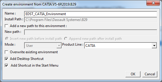
Environment is created and desktop icon is also generated for the same.

  1. The new environment file location is saved at the location:C:\User\hostname\AppData\Roaming\DassaultSystemes\CATEnv
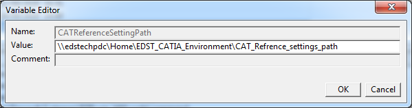
  2. Select Environment (EDST_CATIA_Environment), click on CAT_Reference_settings_path and right click on variable.Click on Edit Variable. Now paste the path copied earlier.
    Customizing CATIA CATSettings-3

    Similarly, copy and paste the same path for CAT_COLLECTION_STANDARD.

  3. Now save the modifications and exit the workbench.Customizing CATIA CATSettings-4

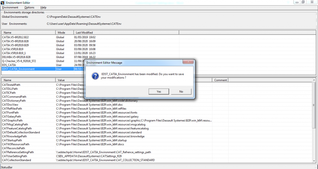
    Now, the modified CATIA Environment is created successfully.

  4. Copy Environment file from C:\User\hostname\AppData\Roaming\DassaultSystemes\CATEnv and paste to the network drive. EDST_CATIA_Environment folder will be created.

The following are the steps to launch CATIA in Admin mode:

  1. Copy and paste the CATIA icon (in this document EDS_CATIA_Environment) on desktop.
  2. Rename EDS_CATIA_Environment to EDS_CATIA_Environment-ADMIN (only for reference)
  3. Right click on EDS_CATIA­_Environment-ADMIN ➜ Properties
  4. Search for CNEXT in target tab and change exe to CNEXT–Admin.exe
  5. Change directory of Environment from “C:\Users\user\AppData\Roaming\DassaultSystemes\CATEnv“–nowindow to EDST_CATIA_Environment -direnv “Network Location“–nowindow for both EDS_CATIA_Environment and EDS_CATIA_Environment –ADMIN icons.
    Changing CATIA environment pathsCustomizing-6

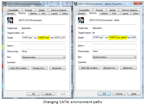
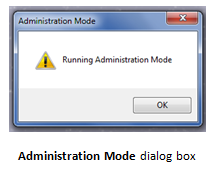
    Now click EDS_CATIA_Environment-ADMIN and CATIA will be opened in Administration Mode.

    Customizing-7

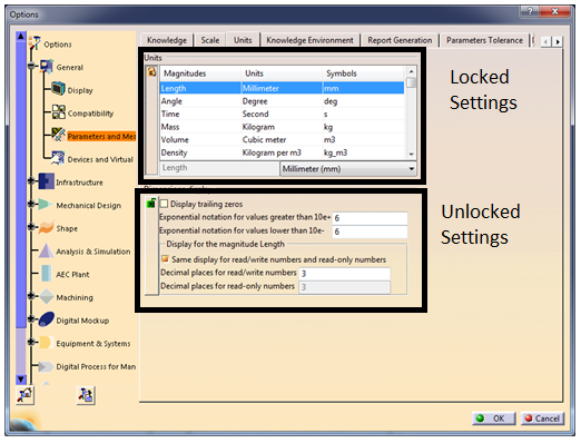
Steps followed to modify System settings:

  1. Go to ToolsOptions
  2. Settings with a lock sign will appear
  3. Modify the required settings
  4. Click on the lock sign to lock the settingsCustomizing-8

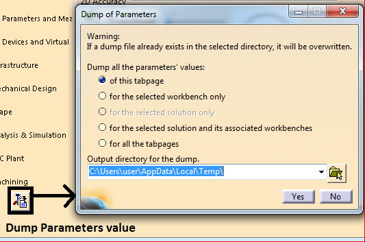
Reset and Dump settings:

  1. This is used to reset CATSettings to default value. User can reset the values which are changed to default. It can be changed for tab, workbench, selected solution and for all tab pages.Customizing-9
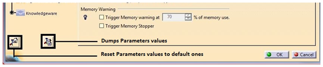
  2. To view values of given settings, comparing settings between different releases and viewing each attribute of settings in detail, dump settings are created. This setting is used to create CATVBS files of settings.Customizing CATIA CATSettings-10

How to Solve CATIA V5 R29 GA Installation Error

When the setup application is launched, Some times CATIA V5-6R2019 GA installation crashes out immediately. This is due to the bug reported in the original installation launcher. In this blog, we learn how to resolve this error while installing CATIA V5 R29 GA.

    1. What is the CATIA V5 R29 GA installation error?

While installing CATIA V5 R29 PLM Express or Legacy configurations, CATIA displays the following error.

How to Solve CATIA V5 R29 GA Installation Error-1
This error occurs due to the redistributable packages installed in Windows 10.

    1. What are the steps to resolve this error?
      • Download any CATIA V5 R29 Service Pack (1 to 5) from DS support portal.
      • Extract the ZIP file.
      • Copy exe file from location:

V5-6R2019.SP1.SPK.win_b64.1-1\SPK.win_b64\1\FIXGA

      • Replace existing exe file in GA folder with the downloaded setup.exe from Service Pack.
        How to Solve CATIA V5 R29 GA Installation Error-2


      • After replacing exe file, CATIA V5 R29 installation starts without any error.

How to Solve CATIA V5 R29 GA Installation Error-3

By downloading and replacing setup.exe file in CATIA V5 GA folder, CATIA V5 R29 can be installed without any error.

How CATIA 3DEXPERIENCE helps in the design of hydroforming-manufactured parts

Introduction:

There is always a challenge to meet the high expectations of auto and aero industry when it comes to the parts. The suppliers need to maintain industry standard accuracy and precision in these parts. These parts undergo processing to achieve the desired component dimensions keeping their end application in mind.

One has to also go through documentation, various processes and extensive quality checks to deliver as per industry standards due to demand in the projects. To ensure this, one can rely on effective and standard engineering processes. One such process is Hydroforming.

Hydroforming process involves a hollow tube of metal (aluminum) placed inside a negative mold that has the shape to be achieved. A hydraulic pump injects fluid at very high pressure in the inner portion of aluminum tube which causes it to expand until it results in the desired shape.

Sheet Hydroforming: This process was originally patented in the 1950s when it was called hydramolding by Fred Leuthesser, Jr. and John Fox.  This process helped to meet the parts supply for auto, aero and other OEMs effectively by easy workability of the process on various metals such as brass, aluminum, stainless steel and low alloy steel. These metals and alloys are lightweight in nature and has high stiffness structurally which is passed on to the finished parts. The hydroforming process can produce complex shapes, stronger, lighter and more robust unibody structures which are predominantly used in parts of automobiles. This process is used in high-end sports car manufacturing industry and in aluminum tubes for bicycle frames.

Hydroforming-1

Advantages:

  • Hydroforming is better compared to solid stamping for manufacturing complex shapes with concavities (which is impossible or difficult with standard solid die).
  • Stiffness-to-weight ratio and lower unit cost of hydroformed parts are some of the other benefits when compared to traditional stamped and welded parts.
  • Generally, cold forming metals like copper, high strength alloys, stainless steel, brass, carbon and aluminum are best suited for hydroforming process.

3DEXPERIENCE CATIA – It helps in achieving the design of parts to be manufactured with hydroforming keeping in mind the process and various industry standards.

The image below shows a typical automotive industry process for car door part. This part is designed using 3DEXPERIENCE CATIA application.

Hydroforming-2

Parts and components are designed with hybrid approach using both surface design and hydro-formed design. One can achieve concepts of surface creation and web creation, detailed design and manufacturing preparation with hydro-formed sheet metal application.

Design Considerations during Design of Rubber Parts

During designing a rubber component, multiple factors need to be taken care of. These factors are as listed: material considerations with required technical specifications and also as per applicability and function, radius and wall thickness, gate location in mould, rib inclusion, mould shrinkage and draft.

    1. Basic Design Aspects (Wall Thickness, Radius, Draft)

While designing rubber components, some basic aspects to adhere to is wall thickness. Most of industry hoses or pipes are made of rubber for carrying some liquid. Where there is liquid flow, it is important to sustain the burst pressure and for that designing right thickness is significant. Smooth flow of the liquid is also important and for that a good amount of radius or curvature can help. Parallelly providing draft helps in smooth ejection of the part as well.

Design Considerations during Design of Rubber Parts-1

    • Corner and Edges: In any design, sharp corners should always be avoided as machining in mould would be difficult due to sharp corners and edges. During part ejection too, it results in lot of part defects as well as mould defects.
    • Undercuts: Sometimes design needs some undercut feature which is an opposite projection of material against tool movement. In rubber components, force ejection can be done up to a certain height for undercut feature. However, the designer should take care of such feature in terms of ejection, long run mould capability, production rate etc.
    • Holes: If any hole should be placed in the designed body, designer can plan for placing metal insert into the mould itself. There is one thumb rule: the height of the hole should not be more than twice of its diameter and the minimum diameter should be about 1.27mm.
    1. Functional Applicability and Environmental Condition

A designer must consider the functional aspect during a rubber component design. The component should be checked whether it will be responsible for 1) any sealing (then compression factor needs to be considered) 2) transmitting some fluid flow (then smoothness and wall thickness should be taken on priority) 3) providing any structural support (then inclusion of ribs inclusion need to be taken care of). There may be various functional aspects depending on which the designer has to define the design.

Design Considerations during Design of Rubber Parts-2

For environmental condition, the designed part will come under the impact of any chemical solvent or from air or water. The designer has to check whether the part is under some dynamic stress or not.

    1. Rubber Material Selection

Material selection is one of the most important aspect in designing any elastomer component because only a best suited elastomer can give the right performance with respect to cost. The life span and durability are two other factors which basically depend on material itself.

Design Considerations during Design of Rubber Parts-3

During material selection, choosing the right elastomer hardness can give the desired result. If the purpose is sealing, then there should be a defined hardness of 70 Shore A. The most common hardness range is 50-80 Shore A. The designer should not always go for very soft or very hard material as the components are being designed with some complicated feature or deep undercut. To account for these features, the component needs the right amount of hardness and for that hardness tester can help.

    1. Moulding Process

For manufacturing rubber components, multiple moulding process are employed. Some of them are compression moulding, blow moulding, injection moulding and transfer moulding.

In compression moulding, material surplus is placed into a cavity calculating the volume of the component and then heat and pressure are applied. Compression moulding is basically chosen for medium hardness compounds with high volume production rate.

Design Considerations during Design of Rubber Parts-4

Injection moulding is the most automated process in moulding technology. In this process, the material is heated and passed through a flowing state and injected into the cavity with high pressure. Injection moulding is the ideal and commonly used process for mass and high-volume production rate.

How to Create Embossing and Engraving in CATIA V5 and CATIA 3DEXPERIENCE

Embossing is a metal forming process for producing raised or sunken designs or relief in sheet metal by means of matched male and female roller dies, theoretically with no change in metal thickness, or by-passing sheet or a strip of metal between rolls of the desired pattern.

Steps to create embossing/engraving in CATIA V5:

In the first step, open a blank drawing file from CATIA drafting workbench. In this drafting file, one has to insert the text that needs to be engraved or embossed. Any font size can be chosen and the text is entered which needs to be created on 3D model as shown below.

Embossing and Engraving in CATIA V5-1

In the second step, this drawing file should be saved as a .dwg/dxf file type as shown below.

Embossing and Engraving in CATIA V5-2

In the third step, the part model to be embossed or engraved can be opened as shown below.

Embossing and Engraving in CATIA V5-3

In the fourth step, the text should be pasted into a geometrical set in the part. This can be done by selecting Fit-in-All command in the View tab.

Now the text can be seen in the part specification tree. If the position of the text is not correct, the Translate function or Rotate command can be used.

Embossing and Engraving in CATIA V5-4

The Translate and Rotate command can be used as shown below.

Embossing and Engraving in CATIA V5-5

In the final step, Pad or Pocket command is chosen to obtain either the embossed or the engraved part.

Part with Embossing:

Embossing and Engraving in CATIA V5-6

Part with Engravings:

Embossing and Engraving in CATIA V5-7

Steps to create embossing/engraving in CATIA 3DEXPERIENCE:

 In the first step, blank drawing file is opened from CATIA native drafting app.
Embossing and Engraving in CATIA V5-8

In this drafting file, the text that needs to be engraved or embossed has to be entered. Any front size can be chosen and then the text which you need to create on the 3D model is entered as shown below.
Embossing and Engraving in CATIA V5-9

This drafting file is exported as a .dwg/dxf file type shown below.

Embossing and Engraving in CATIA V5-10

Embossing and Engraving in CATIA V5-11

The part model that needs to be embossed or engraved has to be opened.
Embossing and Engraving in CATIA V5-12

Next, Text command is used and is oriented along the curve.

Embossing and Engraving in CATIA V5-13

In the final step, Pad or Pocket command is chosen to obtain either embossed or engraved part.

Part with Embossing:

Embossing and Engraving in CATIA V5-14

Part with Engravings:

Embossing and Engraving in CATIA V5-15

Parametric Modelling in CATIA V5

The dimensions in a 3D Model have some relationships or interconnections with each other in Parametric Modelling in CATIA V5. If any one of the dimensions is changed in 3D Model, then all other dimensions will also change in the specified ratio.

Key tools used in Parametric Modelling are:

  1. Parameters
  2. Formulas
  3. Design Table

Parameters

Parameters are the characteristics that control different aspects of geometry and features. Parameters could be of different types such as Length, Area, Mass, Boolean and many more.

Parameters are of two categories:

    1. Intrinsic Parameters:

Intrinsic Parameters are created automatically as we create the geometries and features in CATIA V5.

    1. User Parameters:

In Parametric Modelling, the Parameters which user creates for controlling the dimensions and features are called User Parameters.

 Formulas

Formulas are the relations between different geometrical entities and parameters. For example, to have Inner Diameter as half of Outer Diameter, a formula can be created as:

Inner Diameter = 0.5 * Outer Diameter.

Design Table

Design Table is a text or .csv (Excel) file which contains different set of input values for parameters called configurations. For example, a company has five variants of a product. A design table can be created in which five configurations of input values of parameters can be entered. Selecting each configuration from design table will result in a different variant of the product.

Steps in Parametric Modelling:

    1. Create 3D Model:

Create the 3D Model as per the drawing provided using different workbenches like Sketcher, Part Design etc. In the below image, a tumbler is modelled. The features used in this tumbler are Pad, Pocket and Edge Fillet.

p1

Now, design intent is to design a tumbler in which the same ratio is maintained for all the other geometrical features for any value of outer diameter of tumbler.

p2

    1. Create Parameters:

Create Parameters for input dimensions. For example, in this tumbler there is only one input parameter i.e., Outer Diameter and rest of the dimensions will automatically get adjusted as per the Outer Diameter. Hence, a Parameter of “length” type named Outer Diameter is created. 

    1. Create Formulas: 

Now, Formulas need to be created to interlink various dimensions from the Driving Parameters. In this case, the inner diameter, length & edge fillet of tumbler must change as per the outer diameter of the tumbler. Hence, the following formulas are created: 

      1. Outer Radius of tumbler is linked with the created parameter Outside Diameter as Outer Radius = Outer Diameter/2.

p3

      1. Similarly, a formula is created to control Inner Diameter of tumbler as: Inner Radius = 0.45*Outer Diameter.

p4

      1. Now, a formula is created to control the length of the tumbler by using Pad length as: Pad Length = 2* Outside Diameter.

p5

      1. Finally, a formula is created to control the edge fillet of the Tumbler as: Edge Fillet Radius = 0.05*Outside Diameter. 

p6

    1. Create Design Table: 

Now, it is decided that only four variants of tumblers will be produced of Outer Diameters 35mm, 40mm, 45mm & 50mm. Now, a design table is created that will have four configurations for making four variants of tumblers. In this case, a Design Table can have input values for a greater number of parameters with only one driving parameter.

p7
Design Table can be created either using any pre-existing design file or with current parameter values.
p8
p9

Design table is saved. Now, open the design table and add all the input values of parameters and save it.
p9

Design Table is added under Relations node design in the specification tree. Double click on Design Table:
p11
p12

Now, any configuration can be selected and a new variant of tumbler can be obtained.
p13

Subscribe to our newsletter

Get all the latest information on Events, Sales and Offers.