Links Management in CATIA V5

CATIA link is a dependency relation used to share geometric, parametric or positioning information between components in CATIA V5. Links in CATIA are unidirectional and always point from the child to the parent.

Types of Links

There are five types of links each of which are explained below with a common example.

  1. The CCP link The first CAT Part contains the geometrical definition of the raw material used to create the table leg. The second CAT Part contains the geometrical definition of the finished table leg. Consistency must be ensured between the models: a modification of the raw material must be reflected in the finished leg. For that purpose, the raw material part geometry is copied and pasted in the finished part (with the link maintained), where the machining operations are performed.Since the raw material and the finished leg will never be assembled together, this operation is performed outside the context of an assembly.catia-1

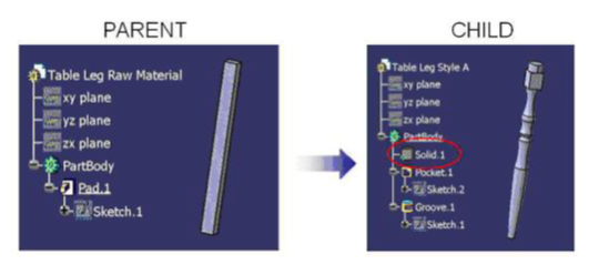
    The CCP link is created in a part when the geometry is pasted using the ‘Paste special as result with link’ functionality provided the copy/paste operation is performed from part to part and outside the context of a product.

    1. The KWE link

The leg socket is the common interface between the table leg and the tabletop. The dimensions of the socket are stored in parameters in the tabletop part. For the table leg to match the tabletop, those dimensions must match. For that purpose, the dimension can be copied (with the link maintained) from the tabletop to the table leg.

catia-2

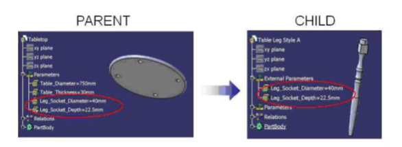
This link is in all points identical to the CCP link, except that parameters are copied instead of geometry.

The KWE link is created in a part where parameters are pasted using the ‘Paste special as result with link’ functionality.

    1. The Instance link

To create a table assembly, the tabletop and table leg components must be inserted in the table assembly CAT Product.
catia-3

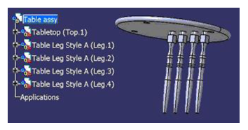
In this process, the table assembly is the parent and the tabletop and table legs are the children. In the table assembly, an Instance link is created for each component. This link carries the name and path of the files.

catia-4

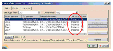
The Instance link is created in a CAT Product where CAT Parts or CAT Products are inserted.

    1. The Constraints

Assembly constraints are used to position the parts of the assembly. Each leg will require an axis-to-axis coincidence and surface-to-surface contact constraints to position it.

catia-5

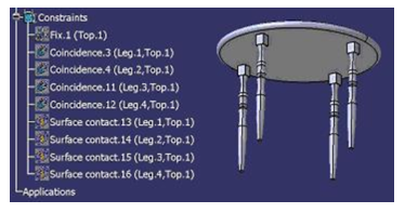
The assembly constraints allow to position parts and products in the context of an assembly. This type of link cannot be visualized in the Edit/ Links menu. The links are stored in the CATProduct and apply to the instance of the components. In other words, an assembly constraint applies to a specific representation of a part in a specific assembly. For example, if the Leg 1 instance is constrained, all the other table leg instances are still free.

If the table leg style A was replaced by a table leg style B in the table assembly, all the constraints would be broken. The use of publications prevents this behavior. If the same publication name (Leg Axis) is applied to both table legs’ axis, the assembly constraint will be reconnected automatically when the table leg is replaced with the second one.

The constraint is created between two part/ product instances. The use of publications will allow reconnecting the constraints automatically when parts are replaced.

    1. The View Link

The table leg CAT Part contains the 3D geometrical definition and a CAT Drawing contains the associated 2D representation. The views are generated from the CAT Part using Generative Drafting functionalities. Whenever the part is modified, the drawing views indicate an update is required to reflect the changes.

This process does not create any external link in the CAT Part (the parent). In the CAT Drawing (the child), a View Link points to the CAT Part (the parent). The View Link is created for each generative view of a drawing. The information carried by the link is the name and path of the source model used for the projection.

catia-6

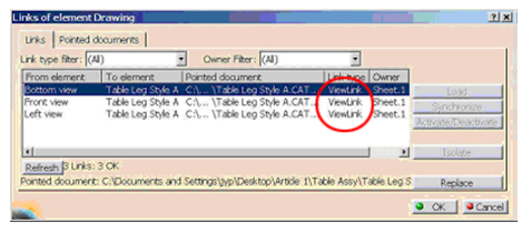
The View Link is created between the CAT Drawing for each generated view. The link points to the object used to create the view (CAT Part or CAT Product)

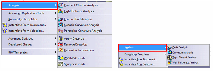
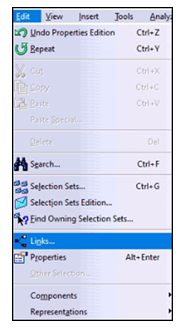
To access Links in CATIA V5, Select Edit ➜ Links.

catia-7
catia-9
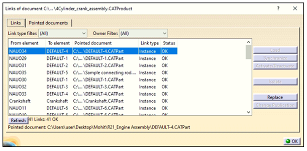
Here, the pointed documents of Assembly, Part and Drawings can be seen.

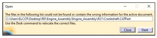
Sometimes when an assembly is opened, an error pops up displaying “File could not be found”. This error occurs when the Part or Drawing File is missing from the location it was kept earlier. This error can be resolved by selecting Desk from error message or Select File ➜ Desk.

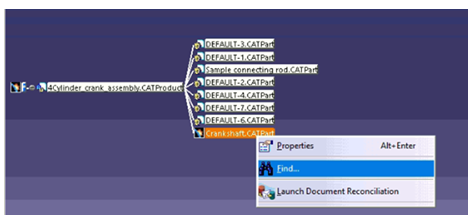
For example, Crankshaft is the missing part in the below error message.

catia--10
catia-11

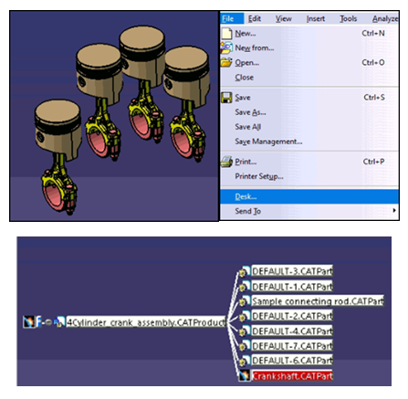
The part file which is highlighted in red color is missing. Right click on the missing part and select Find. Now browse to the path where that file is kept and select the file. The red highlighted part will turn into white color which means that the part is found and loaded in the assembly.

catia-12

Understanding Boolean Operations in CATIA V5

Boolean operation is an important feature in CATIA V5. Types of Boolean operations include Assemble, Add, Remove, Intersect, Union Trim, and Remove Lump.

Assemble

The Assemble command basically works considering the polarity of the solid bodies. One may be interested to know what actually is the polarity of a body. In simple words, it can be said that whenever a new body is created using material formation like pad, shaft and rib or multi-section solid, then that body can be considered as positive polar body. Pocket, groove, slot and remove multi-section solid is considered as negative polar body.

A part body is created as a rectangular block and Body-1 as a solid cylinder as shown below. Consider this Body-1 as positive polar body as it is created using pad command and intersects with part body. Now if we use Assemble Boolean operation, then this cylinder will join the rectangular part body and will act as a single body.

b1

Now again Body-2 is being created as a rectangular block  and is considered as negative polar body because pocket command is used. Whenever Body-2 is assembled with rectangular part body, it will go for material removal in intersected area due to the selection of negative polar body.

b2

Add

Add operation removes only the intersected portion between two bodies so that both parts act as a single body irrespective of the polarity of the bodies. Here, the bodies may be with positive polarity or negative polarity or a combination of both.

Remove

Remove operation removes the selected body first and then is merged with the second body irrespective of the polarity of the bodies. Below is an example on how to create Housing using Add and Remove Boolean operation.

b3

Intersect

 To derive a single body from two different bodies, Intersect Boolean operation is used. Basically, the intersected portion is the output which is displayed as a single body. There is no effect of polar bodies here.

b4

b5

In the above example, there are two sketches intersecting each other in the first picture. In the second picture, pad is created on both sides with a certain limit. After using Intersect Boolean operation, the result shows only the common portion which can be seen in third picture.

Union Trim

Unwanted material can be removed from any two bodies by using Union Trim operation which results in a single desired body.

Consider the example below:

In Model Tree, it can be seen that one rectangular body is intersecting with another circular body and the unwanted intersected area needs to be trimmed. After clicking on Union Trim, it gives an option to the user to keep/remove any face. After selecting the shape to be removed, the result can be seen as below:

b6

b7

Remove Lump

Remove Lump Boolean operation removes the lump inside the body.

During the operation, a tab will give the option to the user to keep/remove any face as required. Using this Boolean operation, a user can remove N number of lump face areas.

Below is an example of creating a lump first by using Remove Boolean operation and then using Remove Lump Boolean operation, it is shown how a lump can be removed.

b8

The image below shows Remove Lump definition tab which allows to choose the particular faces. After selecting the face, result is generated.

b9

For a stable design where design features are interlinked, Boolean operation may be a good operation to go with. After all, design aspect is important as it shows how a designer wants to edit a design in later stages through Boolean operations and allow to modify the particular part where designer wants to modify the part and not the complete body. For product benchmarking where few parameters are changing, changing the particular body can be a timesaver.


Design Considerations during Design of Plastic Parts

Plastic part design consideration plays a significant role in designing and manufacturing a plastic component. Whenever a Product Designer designs a plastic part, it is important to take care of factors such as the moulding process, selection of material, mass manufacturing process and overall area of the part around the functional need by keeping the design intent intact or the end use in consideration.

    1. Overall Area of the Part

While engineering plastics are used in many diverse and demanding applications, the most common design elements or features influencing the overall area includes wall thickness and radius, ribs, bosses, draft etc.

      • Wall thickness and radius: Wall thickness strongly influences many key part characteristics including mechanical performance, appearance, moldability and durability. So, to work with wall thickness, instead of increasing the entire wall thickness, the designer can check whether any kind of ribs, corrugations or curves can be added to get the same strength in the part as with increased wall thickness, as it leads to more weight and less moldability. By providing radius for each element instead of sharp edges, part ejection becomes easier during moulding process. Sharp edges create wear and tear which may result in malfunctioning of the final component after repeated use. The designer can then do a stiffness analysis from Analysis section before finalizing the product design.

p1


      • Ribs and Core Out: In case of rib design, the designer needs to take care of rib thickness. Typically, for a plastic part, rib thickness should be approx. 70% of wall thickness. Along with this, draft and edge radius should also be included. Meanwhile, if there is a complete solid area, the designer can check whether any core out is possible or not as core out gives better manufacturability maintaining right thickness, order and material flow to avoid multiple defects like sink mark, bubbles, fins etc.

p2


      • Bosses and Gussets: For boss design, the most important factor is to plan for the right diameter. As a thumb rule, the outside diameter should be 2 times the inside diameter. Meanwhile, if some bosses need to be placed in flange wall or at an increased height, coring out is the better design practice as it helps to reduce flow hesitation of material during moulding process. Gussets are similar to features boss with an additional stiffener. During design of Gussets, designer needs to take care of the design and ensure that no air traps and material filling arises. Refer below image for the same.

p3

p4


      • Draft: Draft is the most important feature in plastic design. The purpose of providing angles or tapered face by draft is to remove the part from the mould with ease so that it is parallel to the direction of mould release. As a standard, one degree of draft is applied with additional one degree of draft for every 0.0254 mm of texture depth.

p5


The above characteristics are pretty basic consideration for all kinds of plastic design components. In addition to the above characteristics, the designer should always take into consideration the undercuts, sharp corners, core creations etc.

    1. Moulding Process

Plastic moulding is the process of pouring liquid plastic into a mould so that after a specific time, it solidifies in accordance with the provided design shape or customized shape. There are multiple types of moulding processes like extrusion moulding, blow moulding, injection moulding, rotational moulding and compression moulding.

      • Extrusion moulding: In extrusion moulding, hot melted plastic is extruded and pressed through compressed air to get the desired shape. When using this process, the product will continuously have the same shape along the length.

p6

      • Injection moulding: This type of moulding is widely used in the industry. In this process, melted plastic is injected into a designed mould by applying high pressure. Injection moulding is often used for mass production with high levels of accuracy.

p7

      • Blow moulding: With blow moulding, the accuracy level of the finished component is less and thin walled. In this process, air pressure is applied inside the mould to achieve the desired shape.

p8

    1. Selection of Material

In plastic design, material selection is a very important factor. For material selection, one needs to consider application of the part. For example, if in the application area, there is some thermal stress to withstand or some kind of impact to be tolerated, then for those areas material needs to be selected as per that particular requirement.

    1. Mass Manufacturing Process

Defining the right manufacturing method can help in mass manufacturing right quality products which is the final goal for any manufacturer. Here, these two aspects design for manufacturability and design for assembly comes in. This helps to identify the right assembly process – whether the assembly will be done by fitment process or by pressed process.

    1. Parting Line

Defining parting line while designing a part is crucial as this parting line defines the area where the mould in halves during moulding process. Multiple aspects need to be taken care like draft angle, material roughness, any surface finish etc. CATIA has Draft Analysis feature which helps the designer to ensure sufficient draft angle is provided.

p9

    1. CATIA Integration – Analysis

Product iteration is very expensive and time consuming for an injection manufacturing process. In case structural, stiffness or curvature analysis need to be checked, they can be easily done using engineering simulation applications. CATIA Analysis for Designers is one such application which the designer can readily use to check for validating these aspects.
p10

    1. Industry Pain Areas

Most of the plastic product manufacturing organizations face multiple problems during manufacturing. Some common challenges faced by plastic manufacturing organizations are:

    • When a part is to be ejected against the draft direction – in such cases, the designer must be aware of manufacturing constraints and the quantum of force ejection that can be done.
    • When there are multiple no. of lifter or slider arrangements – in such cases, tool designer must analyse the slider movement with respect to time taking into consideration the cooling time. So, in those cases, CATIA Mould Tooling workbench can really be helpful.
    • When designer reverse engineers a product – in such cases, achieving the desired parameter in terms of performance is a challenging task. This can be mitigated by simulating the results through virtual analysis.
    • Assembly of rubber part and plastic part – for a leak proof product, the designer should not prefer the parting line as it creates material flushes in those particular junctions and it results in leakage as well as breakage or tear of rubber parts from inner surface. All these challenges can be addressed beforehand by analysing the parting line position and by doing a mock up.

Subscribe to our newsletter

Get all the latest information on Events, Sales and Offers.