Large Assembly Management in CATIA V5

Working with large assemblies in the CATIA V5 system can be very demanding. Even with the use of extremely powerful machines and workstations, working with large assemblies often leads to the crashing of the system with the error message “Click OK to terminate” appearing. To avoid this error, this blog discusses some recommendations for optimizing the system to minimize the crashing of the program and to make it easy to work with large assembly sets.

  1. Cache System
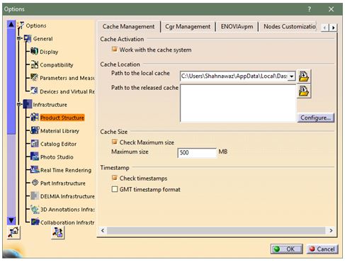
    System’s performance can be increased with the help of cache. When this option is activated, CATIA loads all parts of the set in visualization mode while not loading the whole history of the part. This helps in reducing the load on computer/system memory.

    To activate Cache System, click on Tools ➜ Options ➜ Infrastructure ➜ Product Structure ➜ under Cache Management tab, click “Work with the cache system.”

    large-assembly-1

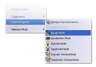
    After restarting the program, CATIA will reload parts in visualization mode. If the part needs to be edited, switch to Design Mode which can be done by right clicking the part and selecting Representations and Design Mode.

    large-assembly-1

  1. CGR Management

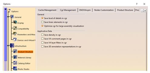
    For large assemblies, CGR formats can be optimized. To optimize CGR formats, click on Tools ➜ Options ➜ Infrastructure ➜ Product Structure ➜ CGR Management tab.

    large-assembly-1

  1. Display Option
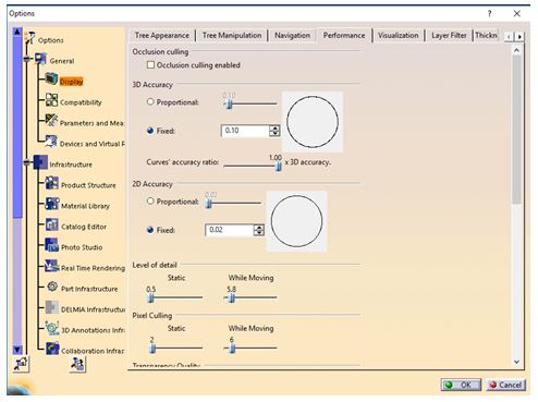
    The changes in display options can be made in Performance Settings tab which will improve the results.

    Click on Tools ➜ Options ➜ General ➜ Display ➜ Performance tab.

    It is recommended to turn off Occlusion Culling and set 3D Accuracy to 0.1 (increase in value improves performance), increase Level of Detail while Moving (increasing the value improves performance), increase Pixel culling while Moving (increasing the value improves performance).

    large-assembly-1

  1. Disable Automatic Saving
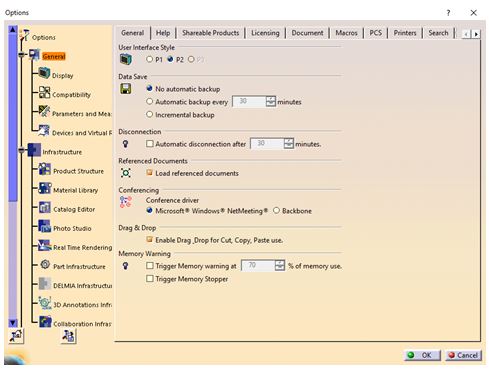
    By default, data is saved every 30 minutes in CATIA. System usually slows down while saving. The automatic data saving can be turned off by clicking  Tools ➜ Options ➜ General tab and turning on No automatic backup in the Data Save settings.

    large-assembly-1

  1. Stack Size
    The total number of “Undo” operations assigned to the CATIA session is the stack size. Reducing this number increases the memory capacity and thus the performance. Stack size can be changed by clicking on the PCS tab in the General menu.

    large-assembly-1

  1. Product Visualization Representation
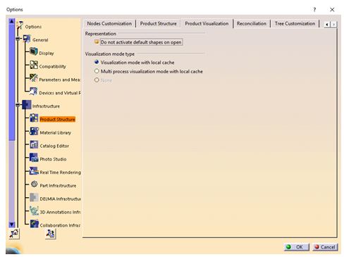
    The memory utilization will improve if sets are open in such a way that all components are deactivated and subsequently activated as needed. To change this setting, Do not activate default shapes on open option needs to be enabled within the Product Visualization (Tools ➜ Options ➜ Infrastructure ➜ Product Structure) menu.

    large-assembly-1

How to Design Complex Aero Parts using the 3DEXPERIENCE Platform?

Designing aircrafts is becoming an increasingly complex task these days. As it becomes increasingly sophisticated, the wiring needed to power and control the electrical systems are also becoming complex.

Large OEMs and companies are dependent on electrical CAD systems which will enable them to execute the electrical diagram which will help in 3D Mock-Up and manufacturing preparation. This will help these OEMs and companies to lower production costs and also to reach the market faster than before.

What are the typical challenges with respect to Wire Harness?

  • Multi applications and different data sources
  • Time consuming, repetitive and error prone creation of electrical system
  • Lack of 3D integration with electrical system schematics which will lead to difficulty in understanding the overall design quality
  • No associativity between 3D wire harness design and its manufacturing

How to Design Complex Aero Parts using the 3DEXPERIENCE Platform1

Due to the complexity and stringent safety regulations in the Aerospace sector, virtual testing and validation plays a significant part in design and manufacturing.

How 3DEXPERIENCE addresses these challenges?

Large OEMs and companies have adopted Dassault Systèmes’ 3DEXPERIENCE platform which accelerates the process from design to manufacturing with compliance to required standards.

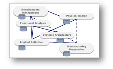
The 3DEXPERIENCE platform provides end-to-end electrical development environment from schematics through 3D design up to manufacturing.

Some of the solutions which the 3DEXPERIENCE platform offers with respect to Wire Harness are described below:

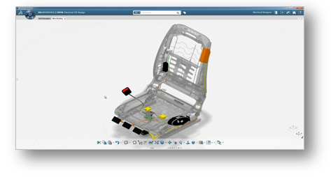
CATIA 3DEXPERIENCE – 3D Wire Harness Design

  • Shared electrical systems data model which enables schematic to 3D Design synchronization
  • Best-in-class 3D wire harness design solution
  • In-context wire harness modelling and simulation
  • How to Design Complex Aero Parts using the 3DEXPERIENCE Platform1

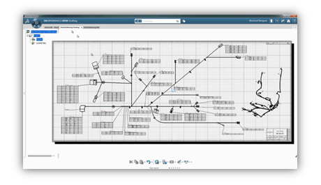
CATIA 3DEXPERIENCE – Harness Manufacturing Preparation

  • World class wire harness layout solution
  • Automatic generation of full-scale drawings for form-board manufacturing
    How to Design Complex Aero Parts using the 3DEXPERIENCE Platform1
  • Synchronization of flattened harness and automatic drawing updates

Large aerospace OEMs and suppliers have reaped multiple benefits by adopting Dassault Systèmes’ 3DEXPERIENCE platform. Some of these are mentioned below:

  • Integrated process coverage to reduce cycle time from design to manufacturing
  • Detect issues in the early phase of design by validating virtually and avoid expensive errors in manufacturing
  • Automatic propagation of modification from design to documentation
  • Quick electrical space reservation within the product to avoid physical prototypes

Thus, the 3DEXPERIENCE platform and its various applications help OEMs as well as suppliers to design and manufacture complex parts rapidly and with accurate precision while adhering to safety standards.

Composite Structure Investigation using ABAQUS Finite Element Solver

Introduction

Composite materials are less expensive and stronger in nature in comparison to conventional materials. They are formed from two or more constituent materials which are different in physical, mechanical and chemical properties. By nature, they are light in weight and extensively employed in spacecrafts, aircrafts, buildings, bridges, racing cars, bathtubs etc.

From a macroscopic point of view, composite materials are anisotropic in nature and require special tools such as numerical tool (FEM) and analytical method or mathematical tool to get insights when under failure, shock, impact or repeated cyclic stresses.

Keeping in mind the complexity and material orientation, this article captures the three-dimensional behavior of composite materials.


Geometry and Meshing

A solid homogenous part is created with internal partition and defined using offset options. Inside the solid homogenous part, a set of matrices are created.

For meshing, 8-node linear brick, reduced integration and hourglass control (C3D8R) were applied as shown in Fig 1.


img1 

Material

Elastic properties under engineering constant are defined during material assignment.

Material, name = “Composite Materials”

Elastic, type = ENGINEERING CONSTANTS

150000, 9000, 9000, 0.34, 0.34, 0.4, 5000, 5000, 5000


Loading and Boundary Conditions

The simulation is performed under static conditions. During the first step, composite structure remains at static conditions. Both sections internally and externally are under static conditions. During the second step, one side of the structure remains under ENCASTRE conditions (U1-U2-U3-UR1-UR2-UR3 = 0). The second side is experiencing a displacement of -5 mm in Z – direction to generate the stress wave propagation as shown in Fig 2. The holistic idea is to see how internal stress is propagating within the structure.

The complete analysis (Pre + Post + Solver) is simulated in ABAQUS/ CAE code.

img2

Results and Visualization

Stress distribution within the internal and external structure is calculated using path feature. Internal matrix experiences slightly lesser tensile stress when compared to external structure under Encastre conditions. Internal matrix which is close to Encastre conditions experiences higher compressive stress.

img3

img3

img5


Mises stress components at integration points

img6

Mises stress components at integration points in S33 direction

img7

Conclusion

The behavior of composite materials is studied using ABAQUS FEM Code. The main objective is to see how the stresses are distributed within the structure (Matrix). ABAQUS helps in predicting the behavior of composite materials subjected to displacement. The approach mentioned in this article can be used in a more complex way by varying the internal matrix dimensions. The matrix can be placed in dissimilar alignment also.

ABAQUS offers higher degree of autonomy in pre- and post-processing. It helps in gaining insights when composite materials are subjected to different conditions.

How CATIA 3DEXPERIENCE helps in the design of hydroforming-manufactured parts

Introduction:

There is always a challenge to meet the high expectations of auto and aero industry when it comes to the parts. The suppliers need to maintain industry standard accuracy and precision in these parts. These parts undergo processing to achieve the desired component dimensions keeping their end application in mind.

One has to also go through documentation, various processes and extensive quality checks to deliver as per industry standards due to demand in the projects. To ensure this, one can rely on effective and standard engineering processes. One such process is Hydroforming.

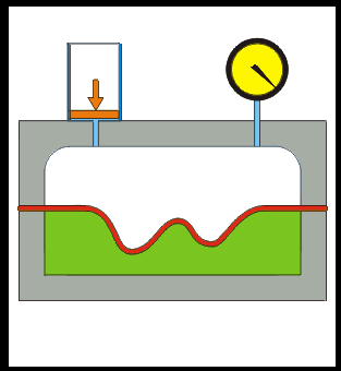
Hydroforming process involves a hollow tube of metal (aluminum) placed inside a negative mold that has the shape to be achieved. A hydraulic pump injects fluid at very high pressure in the inner portion of aluminum tube which causes it to expand until it results in the desired shape.

Sheet Hydroforming: This process was originally patented in the 1950s when it was called hydramolding by Fred Leuthesser, Jr. and John Fox.  This process helped to meet the parts supply for auto, aero and other OEMs effectively by easy workability of the process on various metals such as brass, aluminum, stainless steel and low alloy steel. These metals and alloys are lightweight in nature and has high stiffness structurally which is passed on to the finished parts. The hydroforming process can produce complex shapes, stronger, lighter and more robust unibody structures which are predominantly used in parts of automobiles. This process is used in high-end sports car manufacturing industry and in aluminum tubes for bicycle frames.

Hydroforming-1

Advantages:

  • Hydroforming is better compared to solid stamping for manufacturing complex shapes with concavities (which is impossible or difficult with standard solid die).
  • Stiffness-to-weight ratio and lower unit cost of hydroformed parts are some of the other benefits when compared to traditional stamped and welded parts.
  • Generally, cold forming metals like copper, high strength alloys, stainless steel, brass, carbon and aluminum are best suited for hydroforming process.

3DEXPERIENCE CATIA – It helps in achieving the design of parts to be manufactured with hydroforming keeping in mind the process and various industry standards.

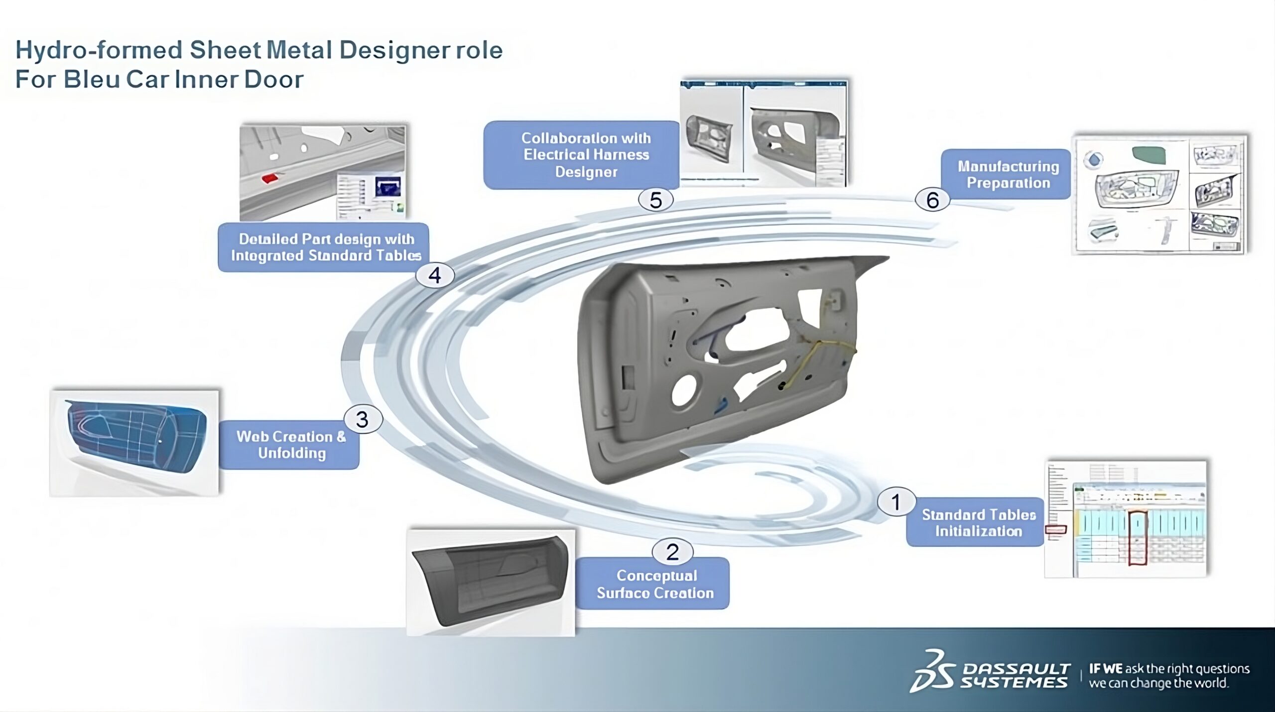
The image below shows a typical automotive industry process for car door part. This part is designed using 3DEXPERIENCE CATIA application.

Hydroforming-2

Parts and components are designed with hybrid approach using both surface design and hydro-formed design. One can achieve concepts of surface creation and web creation, detailed design and manufacturing preparation with hydro-formed sheet metal application.

Design Considerations during Design of Rubber Parts

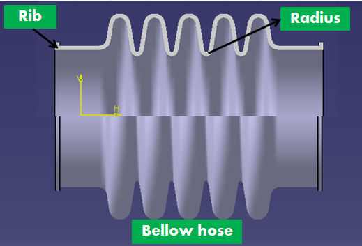
During designing a rubber component, multiple factors need to be taken care of. These factors are as listed: material considerations with required technical specifications and also as per applicability and function, radius and wall thickness, gate location in mould, rib inclusion, mould shrinkage and draft.

  1. Basic Design Aspects (Wall Thickness, Radius, Draft)
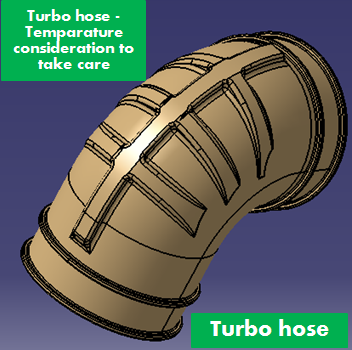
  2. While designing rubber components, some basic aspects to adhere to is wall thickness. Most of industry hoses or pipes are made of rubber for carrying some liquid. Where there is liquid flow, it is important to sustain the burst pressure and for that designing right thickness is significant. Smooth flow of the liquid is also important and for that a good amount of radius or curvature can help. Parallelly providing draft helps in smooth ejection of the part as well.

    Design Considerations during Design of Rubber Parts-1

    • Corner and Edges: In any design, sharp corners should always be avoided as machining in mould would be difficult due to sharp corners and edges. During part ejection too, it results in lot of part defects as well as mould defects.
    • Undercuts: Sometimes design needs some undercut feature which is an opposite projection of material against tool movement. In rubber components, force ejection can be done up to a certain height for undercut feature. However, the designer should take care of such feature in terms of ejection, long run mould capability, production rate etc.
    • Holes: If any hole should be placed in the designed body, designer can plan for placing metal insert into the mould itself. There is one thumb rule: the height of the hole should not be more than twice of its diameter and the minimum diameter should be about 1.27mm.
  1. Functional Applicability and Environmental Condition
  2. A designer must consider the functional aspect during a rubber component design. The component should be checked whether it will be responsible for 1) any sealing (then compression factor needs to be considered) 2) transmitting some fluid flow (then smoothness and wall thickness should be taken on priority) 3) providing any structural support (then inclusion of ribs inclusion need to be taken care of). There may be various functional aspects depending on which the designer has to define the design.

    Design Considerations during Design of Rubber Parts-2

    For environmental condition, the designed part will come under the impact of any chemical solvent or from air or water. The designer has to check whether the part is under some dynamic stress or not.

  1. Rubber Material Selection
  2. Material selection is one of the most important aspect in designing any elastomer component because only a best suited elastomer can give the right performance with respect to cost. The life span and durability are two other factors which basically depend on material itself.

    Design Considerations during Design of Rubber Parts-3

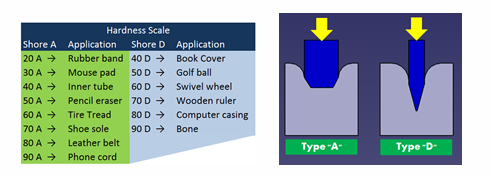
    During material selection, choosing the right elastomer hardness can give the desired result. If the purpose is sealing, then there should be a defined hardness of 70 Shore A. The most common hardness range is 50-80 Shore A. The designer should not always go for very soft or very hard material as the components are being designed with some complicated feature or deep undercut. To account for these features, the component needs the right amount of hardness and for that hardness tester can help.

  1. Moulding Process
  2. For manufacturing rubber components, multiple moulding process are employed. Some of them are compression moulding, blow moulding, injection moulding and transfer moulding.

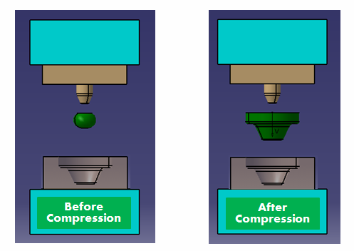
    In compression moulding, material surplus is placed into a cavity calculating the volume of the component and then heat and pressure are applied. Compression moulding is basically chosen for medium hardness compounds with high volume production rate.

    Design Considerations during Design of Rubber Parts-4

    Injection moulding is the most automated process in moulding technology. In this process, the material is heated and passed through a flowing state and injected into the cavity with high pressure. Injection moulding is the ideal and commonly used process for mass and high-volume production rate.

5 Reasons to Adopt Digital Transformation in Farm Equipment Manufacturing Industry

An important success factor for farm equipment manufacturing companies is their ability to define and manufacture quality products tailored to customer preferences and deliver them anywhere in the world at record speed.

A farm equipment assembly can be very complex because it includes mechanical, electrical, hydraulic and pneumatic parts, sheet metal, cabling and automation mechanisms. Some 3D models can have more than 5,000 parts. It also consists of load-bearing frames that require structural analysis.

Need of the hour is to adopt the technology that uses single data driven approach, model-based product backbone that offers digital continuity and governance capabilities – from product engineering to manufacturing to service and maintenance – in one single repository to capitalize knowledge, intensify collaboration, improve productivity and stimulate innovation.

For some companies, digital transformation is a way to get closer to consumers, for others it means accelerating innovation or speeding time to market in order to stay closer to market trends. In any case, organizational process changes paired with modern technologies like PLM, Mobility, Cloud & SaaS can facilitate different ways of working.
download-button

The 5 main compelling reasons to adopt digital transformation are:

  1. Quick Decision-Making and Risk Reduction
  2. Today, organizations need to make quicker decisions and reduce risk at all times. It is important to implement a global, seamless governance also known as invisible governance to make sure all the administrative tasks are automated and transparent as much as possible. This will ensure faster, easier and safer decisions throughout the development cycle.

    5a

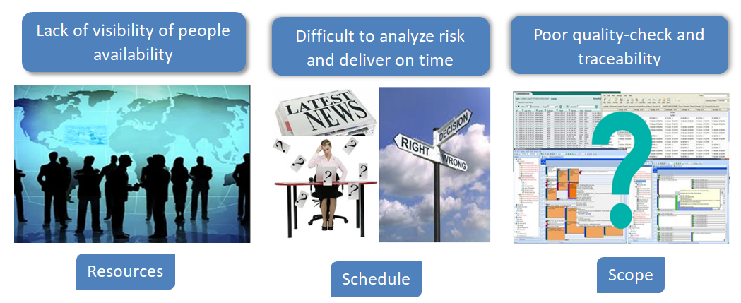
    Organizations are able to plan ahead more easily and also departments can collaborate effectively with the R&D department thereby reducing errors significantly. This reinforces the importance of combining processes and technology to manage development scope, resources, and schedule. When a project is being planned, resources, schedule, and scope are often managed to ensure the current state is not in flux.
    5b

    However, as the project proceeds, new information is gathered that causes adjustments to be made. Suddenly, having disconnected systems for scope, schedule or resources introduces uncertainty.

    If a single technology is used to manage a project’s scope, schedule, and resources, then the risks associated with uncertainty are diminished or avoided entirely.

  1. Improve Engineering Productivity
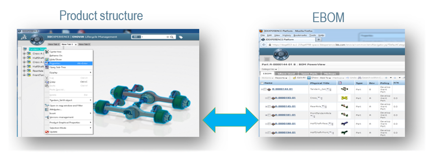
  2. To stay ahead of the latest innovations and market trends, companies must transition from traditional disconnected, discipline specific design and engineering bill of material processes to an approach that supports a single, fully consolidated approach. This helps in fully connected, global view of the combined product design structure and engineering bill of material with consistent global product development business processes.
    5c1

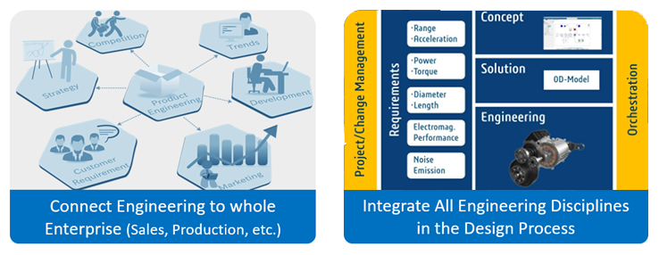
    It is important to manage the engineering definition of products from early definition to final validation in collaboration across disciplines and the value network.

    For this, all the engineering departments are required to be connected to the entire organization, sales, production, R&D, etc. Also, it is needed to integrate all the engineering disciplines in the design process seamlessly.
    5da

    Adopting the digital continuity platforms allows process engineers to co-design the product with product engineers, check consistency of assemblies and improve the process and product quality.

  1. Improve Collaboration among Cross-Functional Teams – Bringing Teams Together
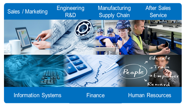
  2. Working in silos between disciplines is a thing of the past. Digital team collaboration is a stimulus for innovation. Engineering teams need an essential set of tools for real-time, secure and structured collaboration on product content. Farm industry needs a scalable, online environment for managing product design, multi-physics simulation and manufacturing process planning with maximum traceability and flexibility.
    5e

    If the information is centrally managed and available to all stakeholders, it improves the competitiveness and resourcefulness to develop innovative products that rapidly respond to farmers’ evolving needs. Establishing a continuous digital thread across the entire product lifecycle empowers everyone to carry out their role to the best of their ability and build each machine first-time right.

  1. Enabling Validation through Virtual Twin
  2. By modelling all the parts in 3D and then sharing this 3D model with the factory ensures accurate assembly of parts. In product architecture, it is possible to represent the kinematics assemblies. It enables to create mobile parts in 3D and make sure they do not interfere with other parts when the assembly is in action. This approach also helps the design team handle changes effectively and rectify errors quickly.

    Thanks to virtual twin, the operators can easily understand assembly of new product variants and also get trained on new processes. It also enables plant managers to take right decisions regarding process schedule, material requirement and also plant maintenance. The customers can also view the products they ordered including all the various options even before it is produced.

    5f

  1. Improving Understanding and Training of Workforce
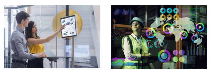
  2. Switching from 2D paper-based processes to 3D digital modelling has completely revolutionized the way today’s factory operators work. Previously, companies used to build a prototype assembly in a testing area to describe in 2D its assembly process, and sort this documentation in folders by product bill of materials. This 2D documentation was used for operator training and to update other operational documentation. Process updates were very complicated.
    5g

    With digital tools adoption, it is easy to simulate assembly operations with overviews, and carry out assembly tests even before the receipt of parts and without any physical prototype. It has become far easier for companies to train their operators and prepare them to work on new models.

    Today, with digital tools, we can run through the entire manufacturing process in detail, operators can be trained on the assembly processes before the product physically exists. When the operators visualize the product and factory model in 3D, they tend to quickly realize the new approach more clearly.

    Adoption of digital transformation is a lot about a strong passion to innovate and excel in your area of work, leveraging exciting new tools to increase collaboration and above all delivering on the objective to serve the customer with the best products.
Subscribe to our newsletter

Get all the latest information on Events, Sales and Offers.