Understanding Boolean Operations in CATIA V5

Boolean operation is an important feature in CATIA V5. Types of Boolean operations include Assemble, Add, Remove, Intersect, Union Trim, and Remove Lump.

Assemble

The Assemble command basically works considering the polarity of the solid bodies. One may be interested to know what actually is the polarity of a body. In simple words, it can be said that whenever a new body is created using material formation like pad, shaft and rib or multi-section solid, then that body can be considered as positive polar body. Pocket, groove, slot and remove multi-section solid is considered as negative polar body.

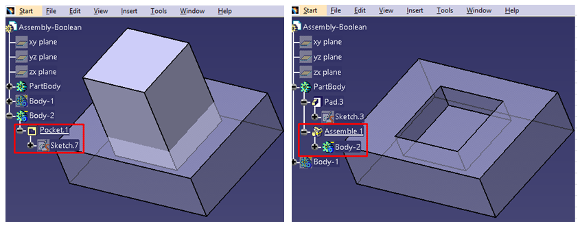
A part body is created as a rectangular block and Body-1 as a solid cylinder as shown below. Consider this Body-1 as positive polar body as it is created using pad command and intersects with part body. Now if we use Assemble Boolean operation, then this cylinder will join the rectangular part body and will act as a single body.

b1

Now again Body-2 is being created as a rectangular block  and is considered as negative polar body because pocket command is used. Whenever Body-2 is assembled with rectangular part body, it will go for material removal in intersected area due to the selection of negative polar body.
b2

Add

Add operation removes only the intersected portion between two bodies so that both parts act as a single body irrespective of the polarity of the bodies. Here, the bodies may be with positive polarity or negative polarity or a combination of both.

Remove

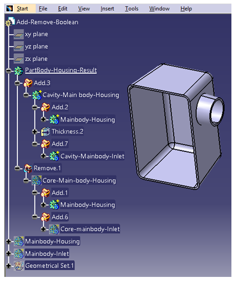
Remove operation removes the selected body first and then is merged with the second body irrespective of the polarity of the bodies. Below is an example on how to create Housing using Add and Remove Boolean operation.
b3

Intersect

 To derive a single body from two different bodies, Intersect Boolean operation is used. Basically, the intersected portion is the output which is displayed as a single body. There is no effect of polar bodies here.
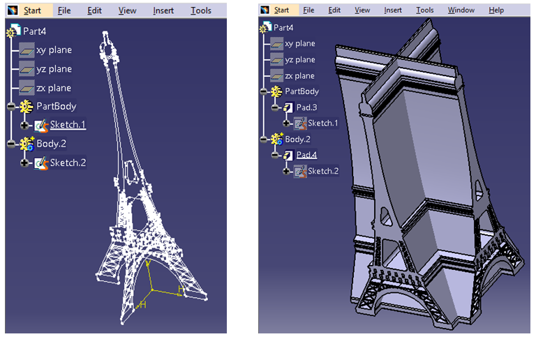
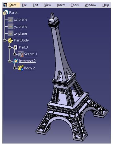
b4

b5

In the above example, there are two sketches intersecting each other in the first picture. In the second picture, pad is created on both sides with a certain limit. After using Intersect Boolean operation, the result shows only the common portion which can be seen in third picture.

Union Trim

Unwanted material can be removed from any two bodies by using Union Trim operation which results in a single desired body.

Consider the example below:

In Model Tree, it can be seen that one rectangular body is intersecting with another circular body and the unwanted intersected area needs to be trimmed. After clicking on Union Trim, it gives an option to the user to keep/remove any face. After selecting the shape to be removed, the result can be seen as below:
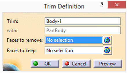
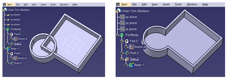
b6

b7

Remove Lump

Remove Lump Boolean operation removes the lump inside the body.

During the operation, a tab will give the option to the user to keep/remove any face as required. Using this Boolean operation, a user can remove N number of lump face areas.

Below is an example of creating a lump first by using Remove Boolean operation and then using Remove Lump Boolean operation, it is shown how a lump can be removed.
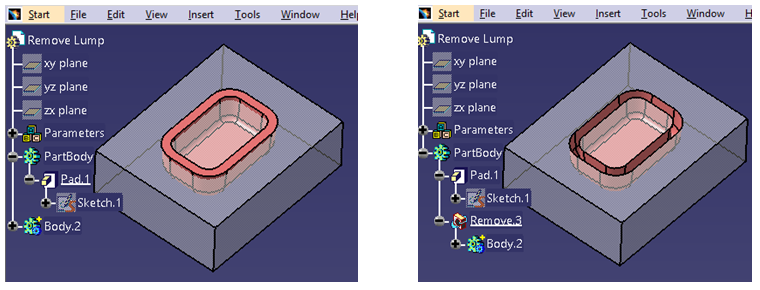
b8

The image below shows Remove Lump definition tab which allows to choose the particular faces. After selecting the face, result is generated.
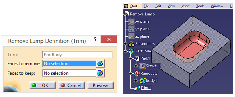
b9

For a stable design where design features are interlinked, Boolean operation may be a good operation to go with. After all, design aspect is important as it shows how a designer wants to edit a design in later stages through Boolean operations and allow to modify the particular part where designer wants to modify the part and not the complete body. For product benchmarking where few parameters are changing, changing the particular body can be a timesaver.
 

Design Considerations during Design of Plastic Parts

Plastic part design consideration plays a significant role in designing and manufacturing a plastic component. Whenever a Product Designer designs a plastic part, it is important to take care of factors such as the moulding process, selection of material, mass manufacturing process and overall area of the part around the functional need by keeping the design intent intact or the end use in consideration.

  1. Overall Area of the Part
  2. While engineering plastics are used in many diverse and demanding applications, the most common design elements or features influencing the overall area includes wall thickness and radius, ribs, bosses, draft etc.

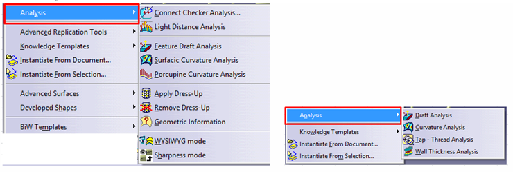
    • Wall thickness and radius: Wall thickness strongly influences many key part characteristics including mechanical performance, appearance, moldability and durability. So, to work with wall thickness, instead of increasing the entire wall thickness, the designer can check whether any kind of ribs, corrugations or curves can be added to get the same strength in the part as with increased wall thickness, as it leads to more weight and less moldability. By providing radius for each element instead of sharp edges, part ejection becomes easier during moulding process. Sharp edges create wear and tear which may result in malfunctioning of the final component after repeated use. The designer can then do a stiffness analysis from Analysis section before finalizing the product design.

    p1


    • Ribs and Core Out: In case of rib design, the designer needs to take care of rib thickness. Typically, for a plastic part, rib thickness should be approx. 70% of wall thickness. Along with this, draft and edge radius should also be included. Meanwhile, if there is a complete solid area, the designer can check whether any core out is possible or not as core out gives better manufacturability maintaining right thickness, order and material flow to avoid multiple defects like sink mark, bubbles, fins etc.

    p2


    • Bosses and Gussets: For boss design, the most important factor is to plan for the right diameter. As a thumb rule, the outside diameter should be 2 times the inside diameter. Meanwhile, if some bosses need to be placed in flange wall or at an increased height, coring out is the better design practice as it helps to reduce flow hesitation of material during moulding process. Gussets are similar to features boss with an additional stiffener. During design of Gussets, designer needs to take care of the design and ensure that no air traps and material filling arises. Refer below image for the same.

    p3

    p4


    • Draft: Draft is the most important feature in plastic design. The purpose of providing angles or tapered face by draft is to remove the part from the mould with ease so that it is parallel to the direction of mould release. As a standard, one degree of draft is applied with additional one degree of draft for every 0.0254 mm of texture depth.

    p5


    The above characteristics are pretty basic consideration for all kinds of plastic design components. In addition to the above characteristics, the designer should always take into consideration the undercuts, sharp corners, core creations etc.

  1. Moulding Process
  2. Plastic moulding is the process of pouring liquid plastic into a mould so that after a specific time, it solidifies in accordance with the provided design shape or customized shape. There are multiple types of moulding processes like extrusion moulding, blow moulding, injection moulding, rotational moulding and compression moulding.

    • Extrusion moulding: In extrusion moulding, hot melted plastic is extruded and pressed through compressed air to get the desired shape. When using this process, the product will continuously have the same shape along the length.

    p6

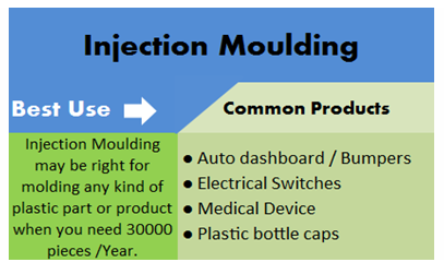
    • Injection moulding: This type of moulding is widely used in the industry. In this process, melted plastic is injected into a designed mould by applying high pressure. Injection moulding is often used for mass production with high levels of accuracy.

    p7

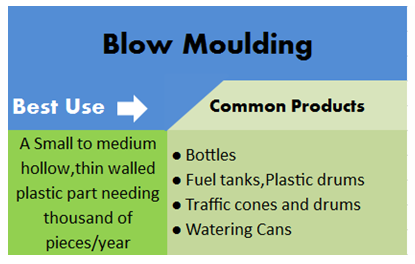
    • Blow moulding: With blow moulding, the accuracy level of the finished component is less and thin walled. In this process, air pressure is applied inside the mould to achieve the desired shape.

    p8

  1. Selection of Material
  2. In plastic design, material selection is a very important factor. For material selection, one needs to consider application of the part. For example, if in the application area, there is some thermal stress to withstand or some kind of impact to be tolerated, then for those areas material needs to be selected as per that particular requirement.

  1. Mass Manufacturing Process
  2. Defining the right manufacturing method can help in mass manufacturing right quality products which is the final goal for any manufacturer. Here, these two aspects design for manufacturability and design for assembly comes in. This helps to identify the right assembly process – whether the assembly will be done by fitment process or by pressed process.

  1. Parting Line
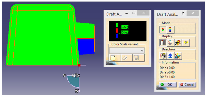
  2. Defining parting line while designing a part is crucial as this parting line defines the area where the mould in halves during moulding process. Multiple aspects need to be taken care like draft angle, material roughness, any surface finish etc. CATIA has Draft Analysis feature which helps the designer to ensure sufficient draft angle is provided.

    p9

  1. CATIA Integration – Analysis
  2. Product iteration is very expensive and time consuming for an injection manufacturing process. In case structural, stiffness or curvature analysis need to be checked, they can be easily done using engineering simulation applications. CATIA Analysis for Designers is one such application which the designer can readily use to check for validating these aspects.
    p10

  1. Industry Pain Areas
  2. Most of the plastic product manufacturing organizations face multiple problems during manufacturing. Some common challenges faced by plastic manufacturing organizations are:

    • When a part is to be ejected against the draft direction – in such cases, the designer must be aware of manufacturing constraints and the quantum of force ejection that can be done.
    • When there are multiple no. of lifter or slider arrangements – in such cases, tool designer must analyse the slider movement with respect to time taking into consideration the cooling time. So, in those cases, CATIA Mould Tooling workbench can really be helpful.
    • When designer reverse engineers a product – in such cases, achieving the desired parameter in terms of performance is a challenging task. This can be mitigated by simulating the results through virtual analysis.
    • Assembly of rubber part and plastic part – for a leak proof product, the designer should not prefer the parting line as it creates material flushes in those particular junctions and it results in leakage as well as breakage or tear of rubber parts from inner surface. All these challenges can be addressed beforehand by analysing the parting line position and by doing a mock up.

Customizing Toolbars and Start Menu in CATIA V5

Customization of toolbars helps a regular CATIA V5 user for executing day to day tasks and also to increase productivity. One can customize the toolbar to include the frequently used commands, so that the user has a smooth and seamless experience while using CATIA. The user need not search for each and every command in the respective toolbar every time. These customized toolbars can be used on any workbenches. There are two ways to do this:

  1. Creating a new customized Toolbar:
  2. In CATIA V5, there is a provision to create a new customized toolbar where one can add frequently used tools and Macros. The main reason for customization is it will save time to access the commands when the user switches the workbenches.

    Go to Tools Customize or right click on any toolbar and select Customize to open the dialog box

    1-Customizing Toolbars and Start Menu in CATIA V5

    Customize dialog box contains the following tabs:

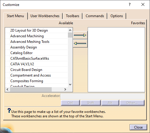
    • Start Menu: This tool is used to customize the Start Menu where one can add the available workbenches to the list of favourites.
    • User Workbenches: Create your own customized workbench.
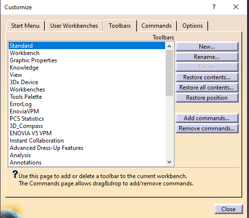
    • Toolbars: Shows the toolbars which are visible currently.
    • Commands: These are the commands one can drag and drop to customize the toolbar.
    • Options: Includes general customization options.
    1. Go to Tools Customize Toolbars tab and select New

    2-Customizing Toolbars and Start Menu in CATIA V5

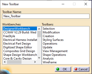
    1. Type the Toolbar Name ➞ Ok.

    3-Customizing Toolbars and Start Menu in CATIA V5

    1. Go to Commands All Commands. Drag and drop the required commands to the New Toolbar as displayed below.

    4-Customizing Toolbars and Start Menu in CATIA V5

  1. Customization of existing Toolbars:
  2. One can drag and drop the command onto a toolbar to add it to the toolbar, and drag away the command from the toolbar to delete it.

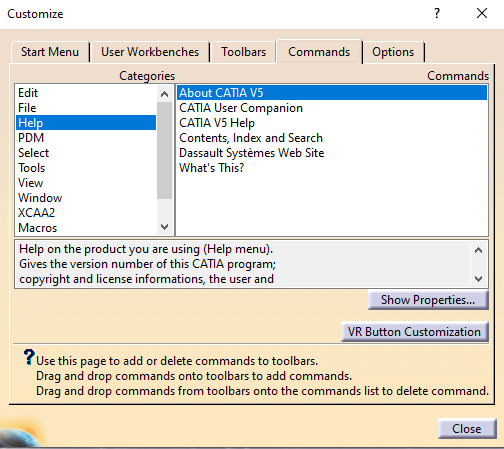
    1. Go to Commands tab which shows the available commands.
    2. One can filter the commands by category, which is listed in the Menu bar.

    By selecting Help category, the commands available under it are visible in the Commands area which is displayed below.

    5-Customizing Toolbars and Start Menu in CATIA V5

    All Commands category shows all commands which are available to use.

    If there is any Macro created, it shows the names too. These Macros can then be added to the toolbar.

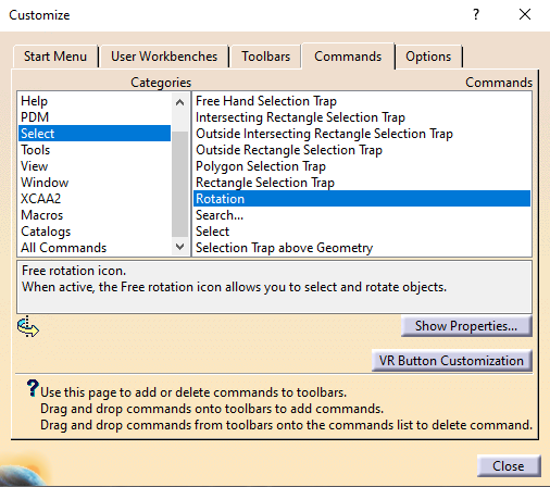
    • Select the required Category and then Command from Commands area.

    The Rotation command is selected as displayed in the picture below. Note the icon of the command and a short help message which explains the role of the icon.

    6-Customizing Toolbars and Start Menu in CATIA V5

    • To add Rotation command to the Standard toolbar, just drag the command from the above window and drop it on the Standard toolbar as shown below.

    7-Customizing Toolbars and Start Menu in CATIA V5

    • To delete Rotation command from the toolbar, drag it away from the toolbar and drop it back to commands list in Customize window.

    The commands which don’t have icons can also be dragged and dropped on to the toolbar where their name will be visible as shown below.

    8-Customizing Toolbars and Start Menu in CATIA V5

    Note:

    • It is not possible to customize the View
    • It is not possible to drag and drop local commands to global toolbars (for example, it is not possible to drag and drop the Pad command to the Standardtoolbar). If one tries, the symbol appears which indicates that this drag and drop is forbidden.
  1. Customizing Start Menu:
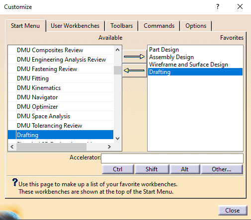
  2. Start Menu can be customized by adding the required workbenches to the favourites list.

    1. Go to Tools Customize ➞ Start Menu tab
    2. From the available workbenches list, add the required workbenches to the favourites list
    3. 9-Customizing Toolbars and Start Menu in CATIA V5

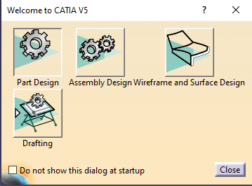
    4. The Start Menu will appear as shown below.
    5. 10-Customizing Toolbars and Start Menu in CATIA V5

Environment Variables in CATIA V5

Environment variables in CATIA are used to customize the CATIA environment as per the user requirements.

There are some Environment Variables which help to start CATIA faster. Though they are not documented, they are used by the user community as they work well with the current supported CATIA release.

To add these variables to your current Windows profile:

  • Right click “My Computer”
  • Click “Properties”
  • Click on the “Advanced” tab
  • Click the “Environment Variables” button which will open a new dialog box
  • Under “User variables”, click on “New”
  • Enter the variable name and values from the list below

These Environment Variables can also be added directly to CATIA environment file at location: C:\ProgramData\DassaultSystemes\CATEnv\CATIA.V5-6R20xx.Byy.

Then save the file and restart CATIA.

The most commonly used variables are:

  1. To disable a CAT Product opening on start-up:
  2. CATNoStartDocument = YES

    e1

    CATIA Startup Screen after using the above Environment Variable:

    e2

  1. To disable the galaxy background at start-up:
  2. CNEXTBACKGROUND = NO

    CATIA Startup Screen after using this Environment Variable:

    e3

  1. To disable the CATIA splash screen on load:
  2. CNEXTSPLASHSCREEN = NO

    If the above Environment Variable is set, CATIA starts without loading the below splash screen.

    e4

  1. If you would like to create a custom or company-specific splash screen, all you have to do is replace the file:
  2. C:\ProgramFiles\DassaultSystemes\Bxx\win_b64\resources\graphic\splashscreens\CATIASplash.bmp

    Replace the above file with the new file where xx is the version of CATIA you have installed.

    e5

  1. CATIA runs console window/Display CATIA’s logs in command window:
  2. CNEXTOUTPUT = console
    e6

  1. The default galaxy background image can also be changed by replacing the file
    C:\ProgramFiles\DassaultSystemes\Bxx\win_b64\resources\graphic\icons\ClientMDIBackgroundNT.bmp where xx is the version of CATIA you have installed.
  2. e7

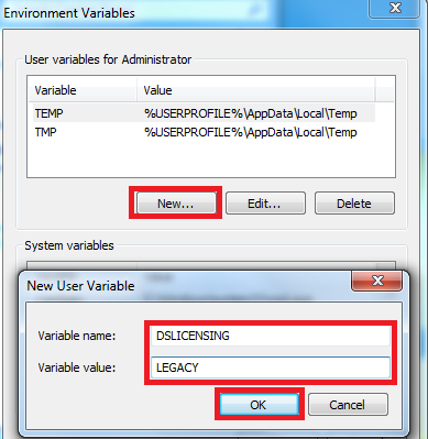
  1. LUM is not supported as a licensing mechanism starting from CATIA V5-6 R2013. In order to use LUM licensing mechanism with CATIA V5 R21 & R22, Environment Variable DSLICENSING with variable value LEGACY should be used by going to Advance System Settings.
  2. e8

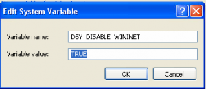
    Also, when using CATIA on Windows XP operating system, to communicate with either DSLS or LUM license server, add the following Environment Variable.

    e9

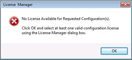
  1. By using following Environment Variable, we can disable license error messages at start-up.
  2. CATLM_ODTS=1

    e10

Performance settings in CATIA V5

There are many ways to manage the performance of CATIA V5 & accuracy of models. To improve performance & increase productivity, we need to configure the settings properly. Some of these options are discussed in detail in this document. These will immensely benefit CATIA users.

  1. Undo Stack
  2. Undo ➞ Stack size ➞ change from 10 to 5

    Stack Size defines the maximum number of commands which can be undone for each document. Lower the value better the performance. More the stack value, more will be the memory consumption.

    Tools ➞ Options ➞ General ➞ PCS ➞ Undo stack size

    a1

  1. Virtual Memory Setting
  2. Virtual memory of the system should be set to recommended value.

    Set trigger memory from 70% to 90%.

    A warning message gets activated when the application detects that the memory consumption exceeds the given threshold.

    a2

  1. Set 2D and 3D Accuracy for Display
  2. 2D and 3D Accuracy settings can be controlled at:

    Tools ➞ Options ➞ Display ➞ Performance

    Set 2D and 3D Accuracy to maximum value (0.5 or 1.0).

    a3

  1. 3D Accuracy Settings for Display
  2. The 3D Accuracy Setting controls the tessellation of surfaces.

    Proportional:

    Calculating tessellation according to object size. The larger the object, the coarser will be the tessellation. For the same accuracy value, the tessellation on small objects will always be finer than on the larger objects.

    Fixed:

    It sets a fixed accuracy value for calculating tessellation on all objects which does not vary with object size.

    Capture1 Capture2

    In Fixed settings option, user can set a sag value (from 0.01 to 10) for calculating tessellation on all objects which does not vary with object size. The sag value defines the chordal deviation for curves and surfaces.

  1. Pixel Culling
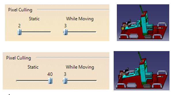
    • The minimum object size in pixels technology is used to define the size in pixels of objects to be displayed or hidden in the geometry.
    • Setting a high value enables to quickly move large parts.
    • Setting a low value displays more details. For example, setting a value of 2 means that objects whose size on screen is lower than 2 pixels are static.

    a7

  1. Anti-Aliasing
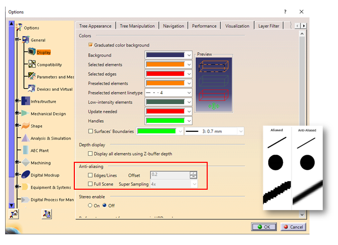
    • This technology is used to smooth out the uneven edges of objects.
    • For better performance, anti-aliasing should be disabled.

    Tools ➞ Options ➞ General ➞ Display ➞ Visualization

    a9

  1. Level of Detail (LOD)
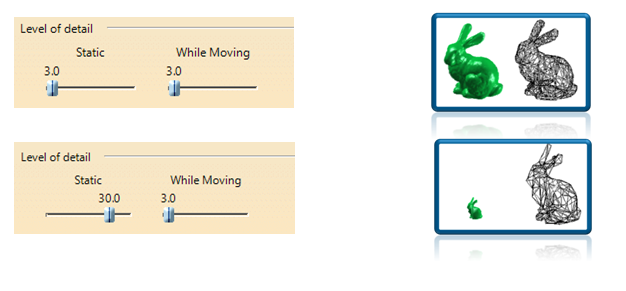
    • The Level of Detail technology or LOD adjusts the polygonal representation of an object to the distance of the user. The idea is that it is not always necessary to view a high level of detail in the geometry because some objects are far away, enough to make the detail meaningless.
    • Set a high value to remove details.
    • Set a low value to see all details.

    a10

  1. Occlusion Culling
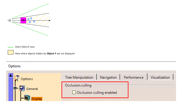
    • The occlusion culling technology improves rendering performance by rendering visible objects only. It is used to detect and prevent occluded objects from being rendered.
    • Occlusion culling optimizes memory consumption and CPU usage.
    • Recommended for large and highly compartmented assemblies.

    a11

    • Use approximate mode for creating views in drafting.

    Tools ➞ options ➞ Mechanical design ➞  drafting ➞ View ➞ View generation mode ➞  approximate view

    • Use CGR management while working on large assemblies.

    Tools ➞ options ➞  Infrastructure  ➞ Product Infrastructure  ➞ Cache management ➞ Check work with cache system

    • Proper CATIA Media Setup

    CATIA V5 64 bit is to be installed on a 64-bit machine. Also install updated service packs for respective release on GA code.

    • Recommended DS Hardware

    System configuration should be as recommended by Dassault Systèmes. Refer the below link.

    https://www.3ds.com/support/hardware-and-software/

    • Cleaning Data

    Assembly cleaning: Regularly clean the assembly as mentioned below:

    Files  ➞ desk  ➞ right click on part/product  ➞  CATDUAV5 ➞  select priority 3 ➞ check clean option at bottom  ➞ RUN

    Repeat this procedure for all parts and products.

    • Corrupted CATSettings

    Delete corrupted CATSetting.

    For Operating System: Windows XP

    C:\Documents and Settings\Administrator (User Name) \Application Data\DassaultSystemes\CATSettings

    For Operating System: Winows7/10

    C\User\Username\App Data\ DassaultSystemes\Roaming\CATSettings

    Delete all files in CATSettings folder (except licensing file).

Using Publications in CATIA V5

With the help of Publications in CATIA V5, one can make different geometrical features available for use in the specification tree.

One can publish a plane, a sketch or a parameter which is not readily visible in the specification tree.

In assembly workbench, during Contextual Design, Publication option becomes very useful.

  1. In CATIA V5, go to Tools ↦ Publication
  2. The Publication command is used to:

    • Publish a geometrical element
    • Edit the default name of the published element
    • Replace geometric element associated with the given name
    • Create a published element list
    • Import this published element list
    • Delete the published element

    Publication dialog box shown below:

    p1

    In Assembly Design workbench, the dialog box also displays a Browse button.

  1. Following geometries can be published in CATIA V5:
    • Wireframe features (Points, Lines, Planes and Curves)
    • Sketches
    • Bodies i.e. part body, other bodies
    • Different Part Design features like Pad, Pocket, and Hole etc.
    • GSD features like Extrude Surface, Fill, and Join etc.
    • Freestyle Design features like Planar Patches, Curves etc.
    • Sub-elements of all geometrical elements like Faces, Edges, Vertices etc.
  1. In the image displayed below, Face is selected as an element to publish which is highlighted in the geometry.
  2. p8

  1. Rename the face as Branch1_Face. The face is published as
  2. p3

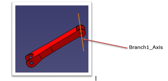
    To publish axes, right-click cylindrical faces and select Other Selection à Axis.

    Rename it to Branch1_Axis.

    sdf

  1. During the use of Publication, one can decide to rename or not rename the elements that are published by using Options menu in the dialog box. Before renaming, one of the following work modes can be set:
    • Never – This is the default option. It will not allow to rename the published element.
    • Always – One can always rename the published element.
    • Ask – The application will ask whether to rename the published element or not.

    p5

    Note:

    • One can rename any element except for axes, edges and faces.
    • Exclamation mark is not allowed for renaming the published element.
  1. Check Ask and click OK to exit.
  2. As shown in the following image, a face and an axis of the CRIC_Branch_1 part has been published.

    p6

    Advantages of using Publications in CATIA V5.

     Publishing geometry has the following advantages:

    • Published geometry can be given a name which can easily be recognized e.g. in case of publishing edges, faces etc.
    • Publications are used to make a particular geometry easily accessible from the specification tree.
    • By using the required setting, only published elements can be used as an external reference if it is the requirement.
    • Publications are very helpful when replacing one component of an assembly with another because published elements having the same name are automatically reconnected during replacement. Else one would have to reconnect them manually if they were not published.

Subscribe to our newsletter

Get all the latest information on Events, Sales and Offers.