Overview on DMLS Process for 3D Printing and its Applications in Space Industry

Additive Manufacturing

Additive manufacturing is a specific 3D printing process where parts are built layer by layer by depositing material according to digital 3D design data. For example, instead of milling a workpiece from a solid block, additive manufacturing builds the part up layer by layer from raw material supplied as a fine powder. This technique is known as Powder Bed Fusion.

Powder Bed Fusion (PBF)

Powder Bed Fusion (PBF) is a laser or electron-based additive manufacturing technique. This is categorized based on the different working systems such as Selective Laser Sintering (SLS), Selective Laser Melting (SLM), Electron Beam Melting (EBM) and Direct Metal Laser Sintering (DMLS). In PBF, DMLS is recognized well in the industrial sectors such as aerospace, defence, automobile, tooling, space launch vehicles, biomedical, electric, and marine. The advantage of the DMLS process is that end components, with freedom of design, higher complexity, tailor-made customization, material reuseable and weighting reduction (lightweight structure) can be manufactured without any change in performance.

Direct Metal Laser Solidification:

DMLS follows the principle of “Direkt Metall Laser Schmelzen” (Direct Metal Laser Melting in English). It is a proven Laser – PBF (LPBF) technology and is now the standard in metal 3D printing. DMLS operates with the principle of high-intensity ytterbium laser beam as an energy source. The laser beam melts the selective powder particles into liquid stages from the melt-pool and gets cured rapidly for the required layer known as a layer thickness. In DMLS, an inert atmosphere (argon or nitrogen) is maintained in the working chamber. Inert gas with high purity has to be used to keep oxygen at the correct level and decrease flammability in the presence of hydrogen. DMLS process is capable producing complex and lightweight structures. The DMLS workflow is displayed below:
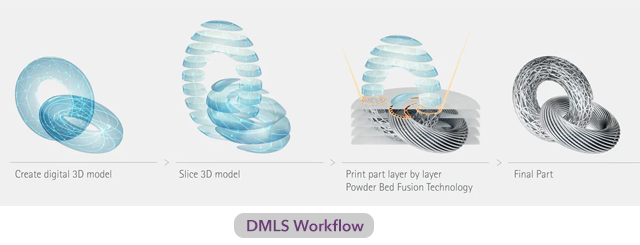
DMLS-4

Feedstock Material widely used in DMLS:

  • Stainless Steel – StainlessSteel GP1, StainlessSteel PH, CaseHardening Steel
  • NickelAlloy – IN718, IN625, HX
  • Cobalt Chrome – CobaltChrome SP2
  • Titanium Ti64
  • Aluminium AlSi10Mg
  • Copper – Pure Cu & CuCrZr

Additive Manufacturing in Space Industry

In space sector, spacecraft and satellites are always looking for new innovations and cutting edge technologies. An increasing number of new start-up companies are entering the space sector. With the knowledge of AM process, they can produce their required designs which are complex while remaining cost-efficient overall.

Benefits of Additive Manufacturing in Space Industry

  1. Design for Additive Manufacturing:
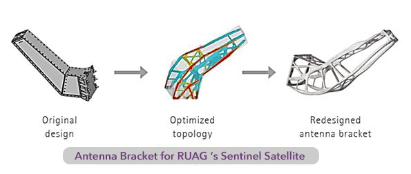
  2. For space launch vehicles, the parts and structures need to be light-weight without affecting the performance. In addition, the functionality of parts can be completely redesigned based on Design for Additive Manufacturing (DFAM) process. For example, multiple parts can be consolidated into a single all-in-one design.
     

    DMLS-4

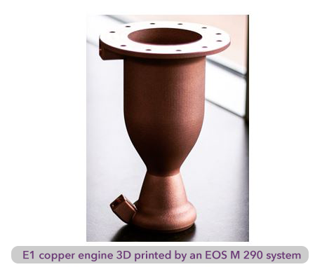
    Currently, many space components and satellite brackets are manufactured through DMLS process to launch small to medium-sized payloads into space more efficiently than ever before. The results include novel and innovative rocket designs and the world’s largest rocket engine to ever be manufactured additively in a single piece. The engine is based on a standard rocket design but is extended with internal ribs for optimal cooling.

  1. Speed and Productivity
  2. In the rapidly growing market of commercial space applications, DMLS processability to manufacture prototypes and small series productions plays a significant role with a lesser lead time and a cost-effective process. There are often extreme customer-specific requirements, particularly on aerospace parts, which perfectly matches the possibilities offered by additive manufacturing.
    DMLS-4

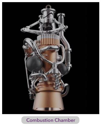
EOS 3D Printed Combustion Chamber for Rocket Engine

Over the past few years, the space sector has blossomed rapidly with many diverse start-ups specializing in development of end components. One of the start-ups based out of US is employing AM process on its mission to orbit. They successfully constructed and tested the new design quickly and cost-efficiently based on their development. The difficulties included the size of the build space and the material properties. AMCM, a company in the EOS group that offers specialized machines tailored to customer requirements, accepted this challenge.
DMLS-4

The combustion chamber, printed with the copper alloy on AMCM’s M4K machines, is the largest single-piece combustion chamber for liquid rocket engines in the world.

The chamber is 86 cm (34 in) high, with an outlet nozzle diameter of 41 cm (16 in).

Manufacturing challenges are addressed by additive manufacturing. This type of part requires higher investment in custom machines. Now, they are utilising the DMLS process to print the combustion chamber, nozzle and neck combined into a single piece.

DMLS technique and its various applications are recognized well in industrial sectors for providing the solutions with new design and manufacturing processes to produce complex parts. DMLS techniques also offer unique process parameter optimization to produce high-quality parts rapidly with intuitive mechanical properties and dimensional accuracy.

Image courtesy: EOS

An Integrated Solution for Manufacturing Complex Parts

Globalization and the fluctuations in customer demand in various industries have made manufacturing companies to rethink their current manufacturing process.

The components are becoming very complex to manufacture since they have to accommodate the growing need of customers’ expectation. How can these complex parts be produced? How can manufacturing companies avoid costly errors? How can companies ensure manufacturing is carried out in the most optimized way?

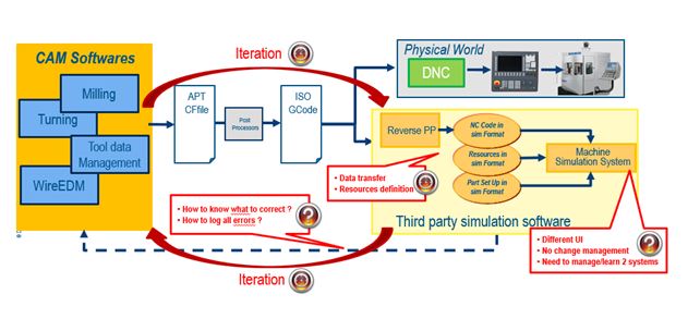
Traditionally, most of the manufacturing companies relied on conventional method which had a lot of silos. Dependency on multiple software solutions delayed the production & increased the production cost.

Traditional workflow:

manufacturing3

Let’s look at the challenges with respect to NC programming:

  • Due to part complexity, product development cost is increased. How can companies reduce this cost?
  • How to efficiently reduce programming lead-time from virtual manufacturing to actual production?
  • How to reduce time-to-market?
  • How to maintain quality and flexibility in a competitive environment?

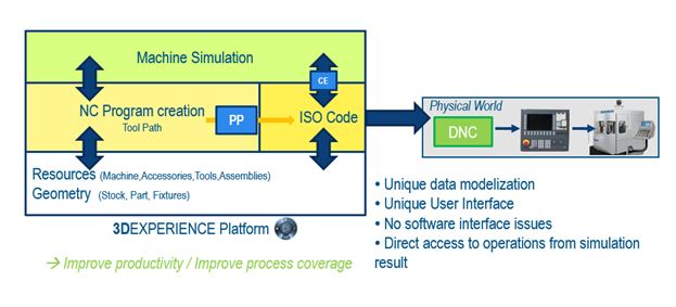
Dassault Systèmes’ NC Programming & Simulation solutions provides unified access from design to manufacturing in a collaborative environment. Dassault Systèmes’ well-known brand CATIA delivers the high-end capability with respect to design & the brand DELMIA ensures the NC code generation, validation & machine simulation under one roof.

NC Programming & Simulation solutions ensure complete work flow from design to manufacturing without the need of any third-party applications.

Benefits of an integrated solution:

manufacturing3

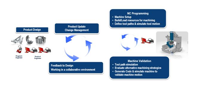
NC Programming & Simulation workflow with Dassault Systèmes’ 3DEXPERIENCE platform

manufacturing3

By adopting Dassault Systèmes’ NC Programming & Simulation solutions which is powered by 3DEXPERIENCE platform, manufacturing companies can address the above discussed challenges and gain the following benefits:

  • Ensure the quality of NC programming, simulation and optimization
  • Increase quality significantly by leveraging NC planning and programming automation
  • Reuse corporate rules and standards for tools & machining process
  • Improve productivity enhancements for tool management, NC setup preparation, NC program creation, NC program validation and NC program simulation

manufacturing3

Smart Factory

Rise in demand, globalization and uncertain pandemic conditions have made manufacturing sector adopt various changes, one of which is smart factory or digital factory. Due to the pandemic, the adoption of digital factory is accelerated across the globe and the actual potential of digital transformation is realized even better now.

What is a Smart Factory?

smart-factory1

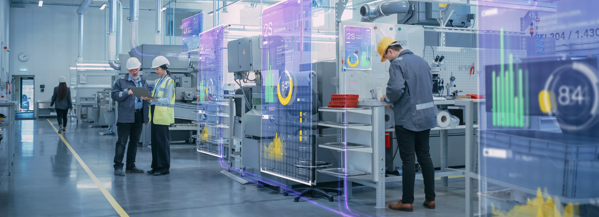
Smart factory leverages digital platform and technology to make significant improvements in productivity, quality, service and flexibility.

Basically, the machines are connected to cloud network with the help of smart sensors. The digital platform gets real time data from all the connected machines through smart sensors to assess the on-going production and also to tackle the risk of machine breakdowns and other unavoidable situations.

How we help customers adopt Smart Factory?

With the manufacturing landscape increasingly customized and demand driven, complex manufacturing processes must be navigated towards achieving cost and production efficiencies. This can be ensured by DELMIA – developed with leading global manufacturers – over 3DEXPERIENCE platform which will give a competitive advantage.

DELMIA delivers four desired outcomes:

  1. CONNECTIVITY
  2. Digital continuity with back office and supply chain systems for fast and accurate change management.

  1. INTEGRATION
  2. Smart data integration with analytics, reporting and visualization across the value chain

  1. CENTRALIZATION
  2. Manage, orchestrate and monitor the full production process with real-time simulation on a 3D virtual shop floor twin.

  1. INFORMED DECISION-MAKING
  2. Intelligent planning, scheduling and resourcing on a smart and data-integrated single source of truth.

Through DELMIA, digital optimization can be achieved of the below 3 operational disciplines:

smart-factory1

  1. DIGITALIZATION OF MANUFACTURING ENGINEERING
  2. Create 3D virtual processes on a data-integrated 3D virtual twin of the shop floor, to minimize risks and maximize opportunities with full operations visibility.

    • Robotics
    • Fabrication
    • Ergonomics
    • Process planning
    • Collaborative manufacturing
  1. ADVANCED PLANNING & SCHEDULING
  2. Enable data-driven what-if scenario planning, and informed decision making.

    • Sales and operations planning
    • Master planning
    • Detailed production scheduling
  1. ENHANCED MES (MOM)
  2. Optimize Manufacturing Execution Systems with smart integration to ERP and machines.

    • Labour
    • Maintenance
    • Warehouse
    • Traceability
    • Intelligence
    • Production
    • Quality
    • Centre of Excellence

Benefits of a Smart Factory:

  • Manufacturing industries get greater visibility
  • More-informed decisions can be taken
  • Achieve faster turnaround times
  • Lower costs

Thus, smart factory leverages digital platform and technology to make significant improvements in productivity, quality, service and flexibility.

5 Reasons to Adopt Digital Transformation in Farm Equipment Manufacturing Industry

An important success factor for farm equipment manufacturing companies is their ability to define and manufacture quality products tailored to customer preferences and deliver them anywhere in the world at record speed.

A farm equipment assembly can be very complex because it includes mechanical, electrical, hydraulic and pneumatic parts, sheet metal, cabling and automation mechanisms. Some 3D models can have more than 5,000 parts. It also consists of load-bearing frames that require structural analysis.

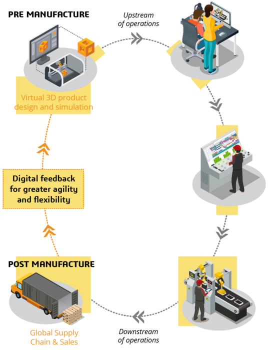
Need of the hour is to adopt the technology that uses single data driven approach, model-based product backbone that offers digital continuity and governance capabilities – from product engineering to manufacturing to service and maintenance – in one single repository to capitalize knowledge, intensify collaboration, improve productivity and stimulate innovation.

For some companies, digital transformation is a way to get closer to consumers, for others it means accelerating innovation or speeding time to market in order to stay closer to market trends. In any case, organizational process changes paired with modern technologies like PLM, Mobility, Cloud & SaaS can facilitate different ways of working.

download-button

The 5 main compelling reasons to adopt digital transformation are:

  1. Quick Decision-Making and Risk Reduction
  2. Today, organizations need to make quicker decisions and reduce risk at all times. It is important to implement a global, seamless governance also known as invisible governance to make sure all the administrative tasks are automated and transparent as much as possible. This will ensure faster, easier and safer decisions throughout the development cycle.

    5a

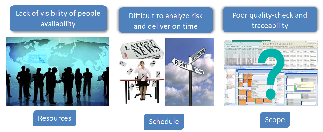
    Organizations are able to plan ahead more easily and also departments can collaborate effectively with the R&D department thereby reducing errors significantly. This reinforces the importance of combining processes and technology to manage development scope, resources, and schedule. When a project is being planned, resources, schedule, and scope are often managed to ensure the current state is not in flux.

    5b

    However, as the project proceeds, new information is gathered that causes adjustments to be made. Suddenly, having disconnected systems for scope, schedule or resources introduces uncertainty.

    If a single technology is used to manage a project’s scope, schedule, and resources, then the risks associated with uncertainty are diminished or avoided entirely.

  1. Improve Engineering Productivity
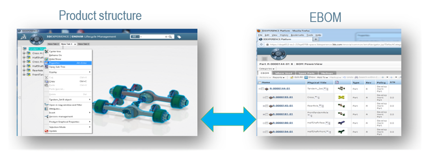
  2. To stay ahead of the latest innovations and market trends, companies must transition from traditional disconnected, discipline specific design and engineering bill of material processes to an approach that supports a single, fully consolidated approach. This helps in fully connected, global view of the combined product design structure and engineering bill of material with consistent global product development business processes.

    5c1

    It is important to manage the engineering definition of products from early definition to final validation in collaboration across disciplines and the value network.

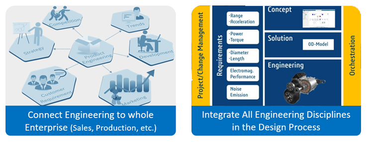
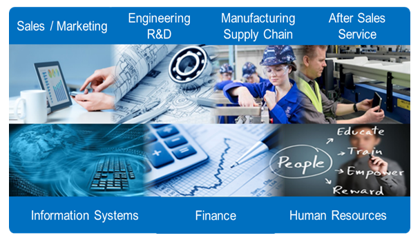
    For this, all the engineering departments are required to be connected to the entire organization, sales, production, R&D, etc. Also, it is needed to integrate all the engineering disciplines in the design process seamlessly.

    5da

    Adopting the digital continuity platforms allows process engineers to co-design the product with product engineers, check consistency of assemblies and improve the process and product quality.

  1. Improve Collaboration among Cross-Functional Teams – Bringing Teams Together
  2. Working in silos between disciplines is a thing of the past. Digital team collaboration is a stimulus for innovation. Engineering teams need an essential set of tools for real-time, secure and structured collaboration on product content. Farm industry needs a scalable, online environment for managing product design, multi-physics simulation and manufacturing process planning with maximum traceability and flexibility.

    5e

    If the information is centrally managed and available to all stakeholders, it improves the competitiveness and resourcefulness to develop innovative products that rapidly respond to farmers’ evolving needs. Establishing a continuous digital thread across the entire product lifecycle empowers everyone to carry out their role to the best of their ability and build each machine first-time right.

  1. Enabling Validation through Virtual Twin
  2. By modelling all the parts in 3D and then sharing this 3D model with the factory ensures accurate assembly of parts. In product architecture, it is possible to represent the kinematics assemblies. It enables to create mobile parts in 3D and make sure they do not interfere with other parts when the assembly is in action. This approach also helps the design team handle changes effectively and rectify errors quickly.

    Thanks to virtual twin, the operators can easily understand assembly of new product variants and also get trained on new processes. It also enables plant managers to take right decisions regarding process schedule, material requirement and also plant maintenance. The customers can also view the products they ordered including all the various options even before it is produced.

    5f

  1. Improving Understanding and Training of Workforce
  2. Switching from 2D paper-based processes to 3D digital modelling has completely revolutionized the way today’s factory operators work. Previously, companies used to build a prototype assembly in a testing area to describe in 2D its assembly process, and sort this documentation in folders by product bill of materials. This 2D documentation was used for operator training and to update other operational documentation. Process updates were very complicated.

    5g

    With digital tools adoption, it is easy to simulate assembly operations with overviews, and carry out assembly tests even before the receipt of parts and without any physical prototype. It has become far easier for companies to train their operators and prepare them to work on new models.

    Today, with digital tools, we can run through the entire manufacturing process in detail, operators can be trained on the assembly processes before the product physically exists. When the operators visualize the product and factory model in 3D, they tend to quickly realize the new approach more clearly.

    Adoption of digital transformation is a lot about a strong passion to innovate and excel in your area of work, leveraging exciting new tools to increase collaboration and above all delivering on the objective to serve the customer with the best products.

Understanding DELMIA Virtual Simulation

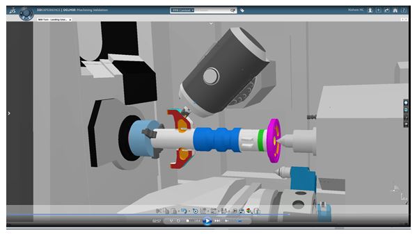
Typically, in a manufacturing organization, after the design stage and before manufacturing, there is a stage involving planning/PPC and manufacturing engineering. DELMIA (Digital Enterprise Lean Manufacturing Interactive Application) helps organizations to do feasibility study and process validations during detailed process planning immediately after the design stage.

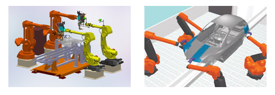
Below are three DELMIA digital manufacturing solutions which can be used in the day-to-day workings of a Simulation Engineer to plan and manufacture.

  • Assembly Simulation
  • While planning for assembly processes, one always needs to take care of feasibility for fitting and disassembly sequence for maintenance purposes. Many organizations perform study on the actual part or the prototype which is expensive and time-consuming. Also, multiple iterations are involved in the study as it is in later stages of design.

    To avoid these challenges, planners can use virtual tools like Assembly Simulation and simulate the assembly and disassembly sequences and check for multiple possibilities. By doing this, they can validate the assemblies for static and dynamic clash, ease of doing maintenance, tool accessibility etc.

    d1

  • Robotics
  • Many organizations use robots for speed, repeatability and accuracy of work or in hazardous environments like welding. Robot programming with technical support for a particular task is a tedious job and it takes the production time of the robot which is expensive due to loss of productivity.

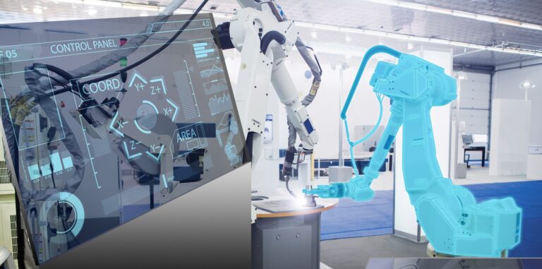
    With DELMIA Robotics, one can teach the robot in the virtual world for welding, material handling, painting, machining, shot peening etc. After validating the program, one can transfer it to the actual robot. After some minor corrections, the robot will work as needed. Hence, the organization can save time and money by using these robots as they can work uninterrupted for a long time.

    d2

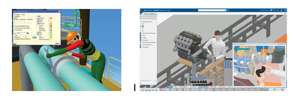
  • Ergonomics
  • There are two aspects in ergonomics:

    1. Ergonomics of the shop floor for comfort and safety of the worker.
    2. Product ergonomics for consumer experience.

    At times organizations do ergonomics study by producing expensive prototypes or apply their learnings from previous experiences. Many times one can observe that workers are not productive because of the work environment. Due to this, there is a productivity loss to the company.

    Using virtual validation of ergonomics, one can improve the work experience of the worker as well as enhance consumer experience. Ergonomics study is useful to ensure comfort, ease of use, reduce fatigue and ensure more productivity. By checking the feasibility and reachability, one can ensure safety and reduction in stress level of the user.

    DELMIA’s ergonomics solutions can help you to do interior design of automobiles and airplanes, work safety analysis and maintenance tasks.

    d3

Save Time, Cost and Improve Accuracy of your Work Instructions by adopting 3D Model-based approach

While there are multiple Work Instructions formats, for the past few years, there is a debate on the suitability and applicability of the appropriate format. This might be the time to put that debate to rest. There are many studies which show that something which is graphic and in pictorial form is more likely to be understood and easier to use. Work Instructions are among the first things which are digitized in Industry 4.0. With the use of right application, it will be an important step for digital transformation and also have a significant impact on manufacturing operations.

What if one could deliver common Work Instructions of multiple configurations to the right people at the right time?

Shop floor deliverables have become much more accurate and precise by using 3D Work Instructions. This was not the case earlier. In the absence of 3D Work Instructions, organizations faced significant loss of time by imparting training to their workforce or making them understand how the system works. It is also not very easy to maintain Work Instructions on paper or in file format. If one compares this with digital Work Instructions, one can see that it is very easy to maintain and minimize the efforts of engineers. These Instructions can be reused for different configurations as well as for different locations considering how rapidly manufacturing processes get changed.

DELMIA Work Instructions help in making:

  1. Operations in sequence
  2. Standard links
  3. Part and tool list
  4. Product and tool list
  5. Markup visual aids

One can also make Work Instructions for machine maintenance, which is majorly of two types:

  1. Preventive Maintenance (PM) includes inspections, condition monitoring, services, and testing.
  2. Corrective Maintenance includes repairs and replacements.

Preventive Maintenance is further broadly classified into three types of tasks:

On-condition tasks – On-condition tasks are used to address specific failure modes of equipment and in most cases seek to determine the condition of equipment and more specifically identifying potential failures associated with the failure mode. This can include inspections, measurements, and condition monitoring.

  1. Fixed interval tasks – Fixed interval tasks are used to address failure modes where the wear-out or failure life is well known and the tasks are performed irrespective of the prevailing condition. These include component change outs that are either refurbished or discarded (as determined during the earlier task development stage), cleaning, lubrication, calibration, and adjustments.
  2. Failure finding tasks – These are used to detect failures of protective devices. These can be safety-related devices or equipment protection devices. Tasks can include manually activating the device such as pull wires on conveyors or limit switches, artificially simulating conditions for the devices such as using synthetic smoke to test smoke detectors, restricting flow for low flow switches, lowering, or raising levels for level switches, injecting electrical current into high voltage overloads or circuit breakers.

Corrective Maintenance Work Instructions

Work Instructions are only used for complex or difficult corrective maintenance. OEMs often provide detailed instructions for maintenance of their equipment in the form of workshop manuals or procedures.

Where a Work Instruction is required, it should contain:

  • The equipment number and description at the lowest level in the equipment hierarchy.
  • Equipment isolation and preparation for maintenance (such as releasing stored hydraulic pressure).
  • A sequence and description of the tasks in sufficient detail so that there is no misunderstanding of what is required.
  • Specifications pertaining to individual tasks (such as bolt tightening torque requirements).
  • Warnings of potential hazards for the maintainer.
  • Damage to the equipment while undertaking particular tasks.
  • Tips on how best to undertake the task (such as positioning or handling).
  • Pictures and diagrams can be very useful, particularly if uncertainty is likely while performing the task.
  • Parts required including Stock Number or Manufacturer Number.
  • Specific tools required.

DELMIA 3D – Work Instructions are increasingly getting adopted by organizations in the present digitized world. At EDS Technologies, we help organizations discover the value of this application and ensure a seamless integration with their digital manufacturing processes. We also encourage to our manufacturing customers to start with DELMIA 3D – Work Instructions which will reduce their time and effort significantly and thereby increase efficiency.

blog2

Subscribe to our newsletter

Get all the latest information on Events, Sales and Offers.