Large Assembly Management in CATIA V5

Working with large assemblies in the CATIA V5 system can be very demanding. Even with the use of extremely powerful machines and workstations, working with large assemblies often leads to the crashing of the system with the error message “Click OK to terminate” appearing. To avoid this error, this blog discusses some recommendations for optimizing the system to minimize the crashing of the program and to make it easy to work with large assembly sets.

  1. Cache System
    System’s performance can be increased with the help of cache. When this option is activated, CATIA loads all parts of the set in visualization mode while not loading the whole history of the part. This helps in reducing the load on computer/system memory.

    To activate Cache System, click on Tools ➜ Options ➜ Infrastructure ➜ Product Structure ➜ under Cache Management tab, click “Work with the cache system.”
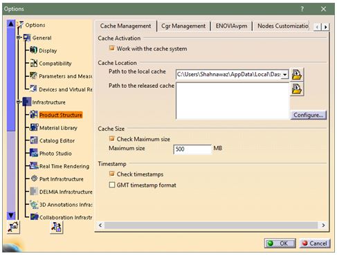
    large-assembly-1

    After restarting the program, CATIA will reload parts in visualization mode. If the part needs to be edited, switch to Design Mode which can be done by right clicking the part and selecting Representations and Design Mode.
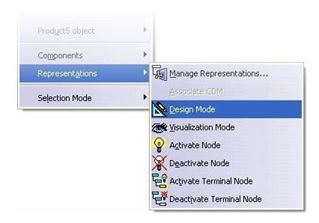
    large-assembly-1

  1. CGR Management

    For large assemblies, CGR formats can be optimized. To optimize CGR formats, click on Tools ➜ Options ➜ Infrastructure ➜ Product Structure ➜ CGR Management tab.
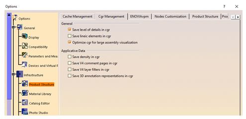
    large-assembly-1

  1. Display Option
    The changes in display options can be made in Performance Settings tab which will improve the results.

    Click on Tools ➜ Options ➜ General ➜ Display ➜ Performance tab.

    It is recommended to turn off Occlusion Culling and set 3D Accuracy to 0.1 (increase in value improves performance), increase Level of Detail while Moving (increasing the value improves performance), increase Pixel culling while Moving (increasing the value improves performance).
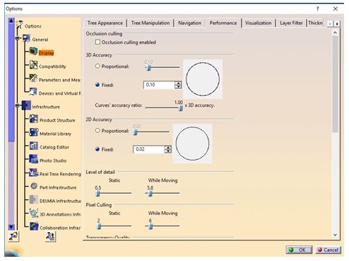
    large-assembly-1

  1. Disable Automatic Saving
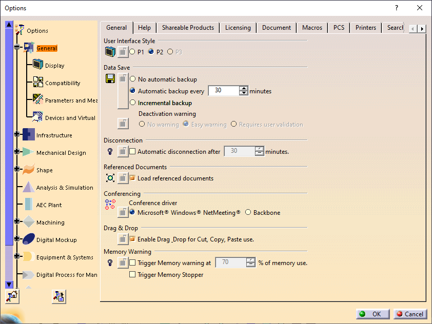
    By default, data is saved every 30 minutes in CATIA. System usually slows down while saving. The automatic data saving can be turned off by clicking  Tools ➜ Options ➜ General tab and turning on No automatic backup in the Data Save settings.
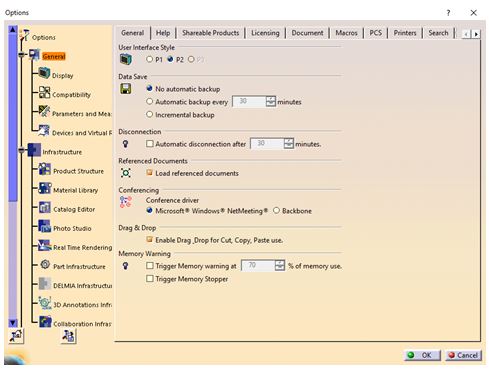
    large-assembly-1

  1. Stack Size
    The total number of “Undo” operations assigned to the CATIA session is the stack size. Reducing this number increases the memory capacity and thus the performance. Stack size can be changed by clicking on the PCS tab in the General menu.

    large-assembly-1

  1. Product Visualization Representation
    The memory utilization will improve if sets are open in such a way that all components are deactivated and subsequently activated as needed. To change this setting, Do not activate default shapes on open option needs to be enabled within the Product Visualization (Tools ➜ Options ➜ Infrastructure ➜ Product Structure) menu.
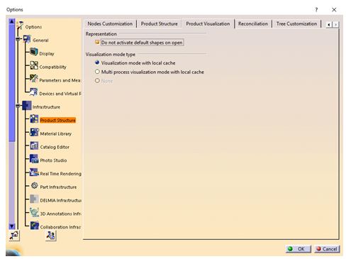
    large-assembly-1

Memory Management in CATIA V5 Drafting

Memory consumption in CATIA V5 drafting depends on the CAD data that is loaded in the CATIA session. The memory consumption increases due to loading of both 2D and 3D data, which further increases due to loading of the data in design mode. This blog focuses on the causes of high memory consumption and the ways to identify and manage the memory consumption issue in case of CATIA V5 drafting workbench.

Memory problem diagnosis in Generative Drafting:

In CATIA V5 Drafting, users generally face low virtual memory condition or the full memory space condition which is indicated by the Operating System error panel when there is no memory or low memory available.

In such cases, CATIA may crash with or without any warning message.

Memory Warning: Warning message appears as per the trigger set by the user in Tools à Options.

m1

The pop-up message warns the user to save the data and exit the session as the available memory is low (the percentage of memory use needs to be set by the user).

Memory save by selecting required “View generation mode”

There are 4 types of view generation mode available in CATIA V5 Drafting.

1. Exact
2. Approximate
3. CGR
4. Raster

m1

Choice of View generation mode:

  1. Exact Mode: This view generation mode is used when fillet edges, threads, exact 2D geometry, complex breakout, unfolded view or associative 2D dimensions need to be created.
  2. Tips to optimize the memory in Exact Mode:

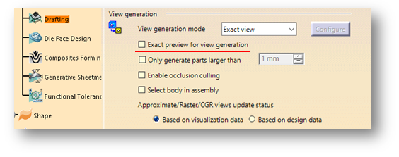
    • Exact preview for view generation: When this option is deactivated, a part or product which is already open in Visualization mode will not be loaded in the design mode for the preview thus optimizing the memory consumption.
    • m1

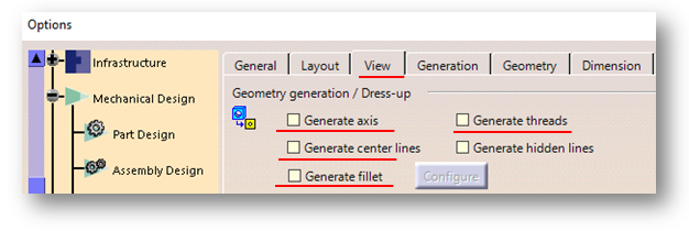
      Geometry generation / Dress-up: Fillet representation, generation of Axis-lines/Centre-Lines/Threads needs to be deactivated if not needed. These elements will not be generated in the views thereby reducing the memory required for the view generation.

      m1

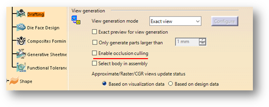
    • “Enable Occlusion Culling” option should be used to hide many instances or bodies. Only the parts visible in the view will be loaded instead of loading all the parts which occurs by default thus saving the memory consumption and CPU usage.
    • m1

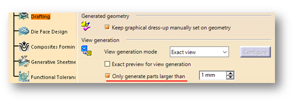
    • If the smallest instances inside the product structure need not be loaded, “Only generate parts larger than” can be used to filter these small instances.
    • m1

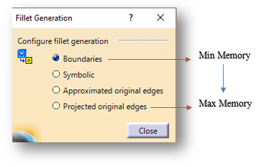
    • Different fillet projection modes have varied memory consumption. “Boundaries” option as shown below requires the least memory consumption whereas “Projected original edges” requires the maximum memory in fillet generation.
    • m1

  1. Approximate Mode:
    • Approximate views are lower in precision and quality when compared to exact views. This mode reduces the memory consumption and improves the system performance.
    • Approximate view consumes lesser memory than CGR.
    • Approximate view generation is faster than CGR.
  1. CATIA Graphical Representation Mode:
    • CGR views are generated by using the Visualization data. It is only the graphical representation of the geometry.
    • CGR views are lower in quality when compared to exact view and consume less memory during generation. However, the view generation is little slow.
  1. Raster Mode:
    • Raster views are generated as images. This helps to quickly generate views for large products or assemblies, regardless of drawing quality.
    • This mode consumes very little memory. This does not load the parts in the design mode. If only an overview is needed, Raster mode is used to get a 2D geometry image.

How to Ensure Uninterrupted Analysis in Abaqus by using Restart Analysis?

The one aspect which is the most desirable while performing an analysis is that it should complete without any errors or interruptions. However, this is not the case. While performing any analysis, there are several interruptions more often than not like large memory, machine crash etc. To rectify these errors and minimize interruptions, there is a concept called Restart Analysis in ABAQUS.

Restart Analysis in ABAQUS helps to continue the previous analysis by the help of restart file. Any type of analysis can be restarted which is terminated at any particular level.

The following points need to be considered to restart an analysis in ABAQUS:

  • The user should plan initially and need to request restart output before the running the previous analysis
  • This request will generate .res file in work directory. Restart file allows previous analysiswith a new analysis.
  • Model used during the Restart Analysis should be same as previous analysis. Any modification with respect to geometry, mesh, material, loads, etc is not recommended.
  • Each step of the Restart Analysis reads the old file data which is available in the .res file and writes a new one.
  • All the loads and boundary conditions from the previous analysis remain unchanged in Restart Analysis as well.
  • If ABAQUS restarts the analysis from an unfinished step, it will try to finish that step first and then the remaining steps to complete the Restart Analysis.


To run Restart Analysis in ABAQUS, the following steps need to be followed:

  1. Request restart output before running the previous analysis. Switch to step module, choose the Output Request in the main menu and select Restart Output. Enter “1” under the frequency for requesting the restart file in Step 1. If there are multiple steps, the file can be requested by entering the same inputs.
  2. c1

  1. After pre-processing the model, job should be edited as “Job1” with analysis type as “Full analysis”. This run will generate .res file in the work directory which will be used for Restart Analysis.
  2. c1

  1. To start Restart Analysis, right click on Model and select Edit Model Attributes. The job name of previous analysis needs to be entered and the exact step name from which the analysis needs to be restarted (terminated step name).
  2. c1

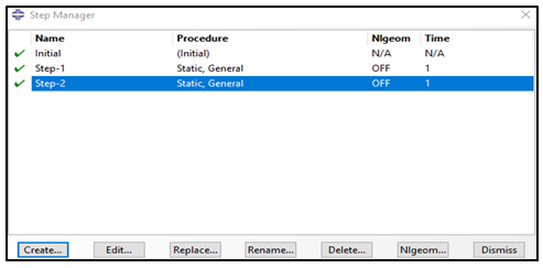
  1. Create a step to run the Restart Analysis. Here, Step 2 is created and is used in Restart Analysis in ABAQUS by taking data from the previous job.
  2. c1

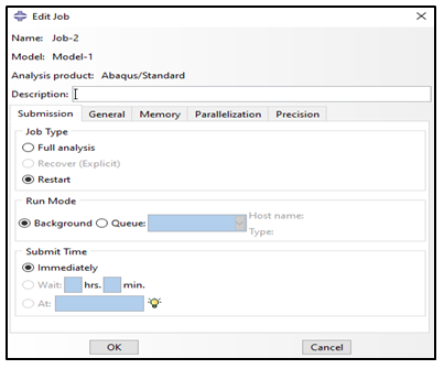
  1. Run Restart Analysis by creating a new job and choose the job type as “Restart Analysis”. The analysis will continue from the termination point of previous analysis.
  2. c1

    When complex analyses with large models are being run, they require more time to complete and often there are chances it might terminate at some particular step. It is efficient and recommended to use Restart Analysis in such type of problems because if the analysis terminates at a particular step, the whole analysis need not be run again. By using Restart Analysis, time and cost can be saved by restarting the analysis from the termination point.

How a startup can thrive in the market?

Startups come up with new designs and inventions. However, qualifying them as a viable product in a short period of time and preparing them for production and commercialization has many challenges.

Some of the challenges could be:

  1. Design finalization and approvals as per industrial standards
  2. Prioritizing consumer experience
  3. Overcoming expensive physical validations
  4. Achieving the first-mover advantage
  5. Getting stabilized in the market while competing with big players

The above challenges can be addressed by a few ways. They are explained below:

  1. Startups get lot of support from the government for developing Electric Vehicles, Drones and UAVs. They should approach the right people, utilize, validate and adopt the right digital solutions at the right time to address the market demands.
  2. Adopting cloud technology is one solution which gives flexibility to the stakeholders to connect from wherever they are.
  3. Adopting model-based design solutions where design, engineering, manufacturing, marketing, purchase and finance are on the same platform which will reduce the time-to-market by eliminating all non-value-added tasks.
  4. From market study, concept design digital definition, digital Validation, process planning, product development to customer experience, it is difficult to adopt different applications by a startup and deliver the product to the market on time. To simplify and expedite the process, Industry Solutions Experience and Industry Process Experience can be opted as per startup requirements which are available in 3DEXPERIENCE platform. With this combination, design, engineering, manufacturing, governance and marketing solutions are available on a single platform with cloud environment


Industry Solutions Experience and Industry Process Experience are beneficial to startups. They are explained below by taking the examples of EV and Aero-related startups:

  1. There are few of the Industry Process Experience as a package like ELECTRO MOBILITY ACCELERATOR for the EV startups. The complete workflow is given below:
    a1
    • Over 50 percent of programs in Aero-related startups (UAVs, drones) miss their deadlines. Programs are often delayed due to issues being discovered during the manufacturing process that could have been prevented in the design phase. To significantly increase competitive advantage, startups can opt for Co-Design to Target solution under Mechatronics Systems Engineering or Component Functional Generative Design for Additive Manufacturing.
      a2

How to perform Geotechnical Analysis of Soil using ABAQUS

The analysis of geotechnical problems is rather complex due to stress dependent material behavior and varying stiffness for loading and unloading conditions. Generally, soil has three different phases which are soil skeleton, pore air and pore water which often lead to complex interaction mechanism. Also, large deformation of soil continuum is observed under loading. Such complex behavior, boundary and material modelling can easily be found out and addressed by ABAQUS.

This blog mainly focuses on ABAQUS capabilities of soil modelling, material modelling, complex loading analysis, boundary modelling and analysis procedures used in geo-mechanics by taking the example of a laterally loaded pile.

Characteristics of Soil:

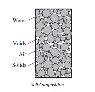
How to perform Geotechnical Analysis of Soil using ABAQUS-1

The typical granular soil composition is of three components viz solid, liquid, and gas. The solid components of soil are solid grains (resultant of weathered rocks). The liquid component is usually pore water (pore fluid), and the gas component is usually air. The gaps between the solid particles are called voids.

When soil is loaded, the pressure in pore fluid gets modified due to which the pore fluid flows and leads to the deformation of soil over a period of time. This deformation of soil can be analyzed by using mechanical and permeability properties of soil along with pore pressure boundary condition in ABAQUS.

Loading Conditions:

Material behavior of the soil is rather complex when compared with other engineering materials. Soil can be differentiated like granular soil (sand and gravel) and soft soil (clay or silts). When granular soils are loaded slowly, there will be a change in volume which results in excessive pore pressure that dissipates rapidly due to high permeability and is called as “Drained Loading”.

On the other hand, when soft soils are loaded, it generates excess pressure which is entrapped inside the pores because of low permeability. This condition is known as “Undrained Loading”. Generally, both loading conditions can be carried out in laboratory by using Tri-Axial test setup. Therefore, in numerous simulations, this complex behavior has to be taken into account.

Material Models:

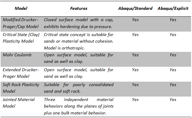
Several material models are available in ABAQUS including elastic, plastic, pore fluid, concrete damage plasticity, concrete smeared cracking and plasticity models as discussed below.

How to perform Geotechnical Analysis of Soil using ABAQUS-2

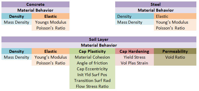
ABAQUS built-in material model can deal with applications where fully coupled conditions are needed to simulate. There are exceptions where large deformation needs to be modelled with special techniques such as Discrete Element Techniques (DEM). Also, user defined material can be incorporated with VUMAT, UMAT framework. For laterally loaded pile, the following properties are used.

How to perform Geotechnical Analysis of Soil using ABAQUS-3

Contact Interaction for Geotechnical problem:

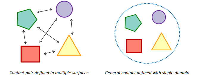
ABAQUS provides two algorithms for modeling contact interaction:

  1. Contact pair algorithm – it is used where every possible surface pair has to define contact interaction including surface which may come in self contact. It is also based on master-slave definition.
  2. General contact algorithm – it allows to define many or all regions with single interaction properties. This algorithm automatically decides master-slave surfaces.

ABAQUS also gives flexibility to find contact surface automatically within chosen parts or whole model.

How to perform Geotechnical Analysis of Soil using ABAQUS-4

In geotechnical analysis, where blast loading is carried out to analyze the structure load bearing capability, Eulerian domain needs to be defined. In such scenario, general contact has to define and it works very efficiently.

Element Selection:

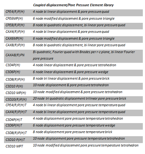
To model fully or partially saturated fluid flow through a deforming porous medium, ABAQUS provides Pore Pressure Element type which can be used for soil and geostatic analysis. These elements have both displacement and pore pressure degrees of freedom. In second-order elements, the pore pressure degrees of freedom are active only at the corner nodes. Pore Pressure Elements are available for plane strain, axisymmetric, axisymmetric-asymmetric and for three dimensional problems.

How to perform Geotechnical Analysis of Soil using ABAQUS-5

Analysis Procedure:

ABAQUS Standard provides two different procedures to analyze the soil problems viz “Geostatic” & “Soil”. Also, soil like material, in case of large deformation, can be simulated using special techniques like

  1. Coupled Eulerian-LaGrangian Techniques (CEL)
  2. Smoothed Particle Hydrodynamics Techniques (SPH)
  3. Discrete Element Techniques (DEM)

Above techniques can be used for offshore foundation, crushing of soft rocks, mining & agricultural industries respectively. For laterally loaded pile the “Geostatic” & “Soil” procedures are used for analysis.

“Geostatic” procedure is normally used as the first step of a geotechnical analysis; in such cases gravity loads, initial stress state, void ratio distribution or saturation are applied during this step. Ideally, the loads and initial stresses should exactly equilibrate and produce zero deformations. The geostatic procedure requires that the initial stresses are close to the equilibrium state; the displacements corresponding to the equilibrium state might be large. “Soil” procedure is used to specify transient (consolidation) or steady-state response analysis of partially or fully saturated fluid-filled porous media.

Save options in CATIA V5

There are multiple ways to save a document in CATIA V5. It sometimes depends on organization guidelines. In this blog, multiple options of saving a document in CATIA V5 are discussed. For saving a CATIA V5 document, three options are available. Click on Tools ➜ Options ➜ General ➜ under General tab ➜ Data Save to access these options. The save options are as follows:

  • No automatic backup
  • Automatic backup every ___ minutes
  • Incremental backup

Save options in CATIA V5-1

No automatic backup

The documents here are not saved automatically.

Automatic backup

This is the option which is enabled by default and user can choose after how many minutes data should be saved automatically. It depends on the user what save frequency he wants.

The default value given here is 30 mins.

Incremental backup

This option is not available for all the workbenches. In this case, the documents that are open are stored in a directory which is temporary. It enables data recovery up to the last interaction.

Other Ways to Save a Document in CATIA

Save

This option is used to save a current file.

Save All

This option is used to save every part or product for each modification.

Save As

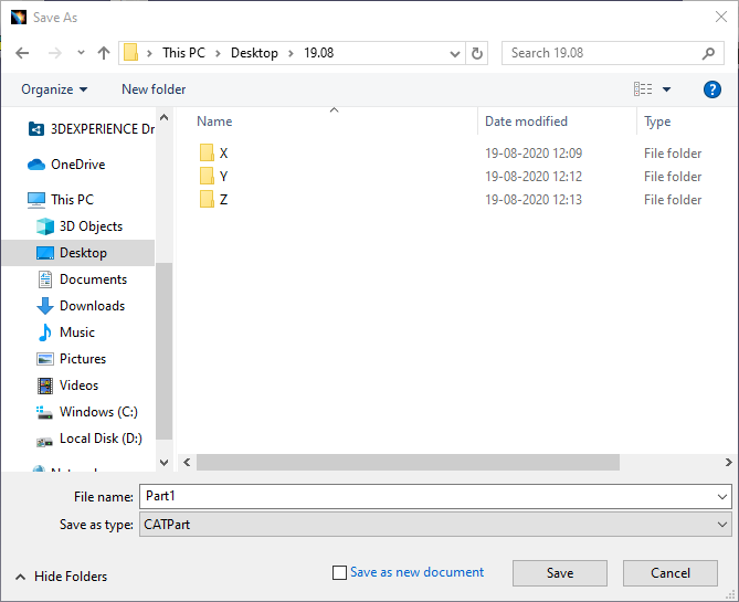
Dassault Systèmes CATIA V5 has a native part file format of CATPart but the application allows users to save the part in other formats like STEP and IGES allowing exchange of CAD data using a common file type.

Save options in CATIA V5-2

Save Management

This is used when there are complex or large assemblies to save the data storage time. The use of Save Management functions is recommended when there is a large assembly with multiple parts. The reason for this is the complexity. Using normal Save, entire model will be restored, which lengthens the data storage time in case of complex assemblies and results in large amounts of data.

Saving data using the Save Management function will save only new and modified parts. Unchanged parts will be preserved and there is no need to restore the same data. This feature shortens storage time, which is particularly important when storing large and complex models/sets on the server.

Save options in CATIA V5-3

Propagate Directory

This option saves the complete model or assembly to a new location in the same folder. If we edit or make a change it will be done in the selected folder and all parts of the assembly will also be copied to the main assembly location.

Save options in CATIA V5-5

Saving files in lower version

Many a times there will be a requirement of saving files in lower version as the person to whom it is shared may not be having the same release.

For this, the downward compatibility option is used.

Select the desired option and save.

Click on Tools ➜ Downward Compatibility ➜ Save

Save options in CATIA V5-5

Subscribe to our newsletter

Get all the latest information on Events, Sales and Offers.