Using Publications in CATIA V5

With the help of Publications in CATIA V5, one can make different geometrical features available for use in the specification tree.

One can publish a plane, a sketch or a parameter which is not readily visible in the specification tree.

In assembly workbench, during Contextual Design, Publication option becomes very useful.

    1. In CATIA V5, go to Tools ↦ Publication

The Publication command is used to:

      • Publish a geometrical element
      • Edit the default name of the published element
      • Replace geometric element associated with the given name
      • Create a published element list
      • Import this published element list
      • Delete the published element

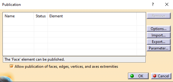
Publication dialog box shown below:

p1

In Assembly Design workbench, the dialog box also displays a Browse button.

  1. Following geometries can be published in CATIA V5:
    • Wireframe features (Points, Lines, Planes and Curves)
    • Sketches
    • Bodies i.e. part body, other bodies
    • Different Part Design features like Pad, Pocket, and Hole etc.
    • GSD features like Extrude Surface, Fill, and Join etc.
    • Freestyle Design features like Planar Patches, Curves etc.
    • Sub-elements of all geometrical elements like Faces, Edges, Vertices etc.
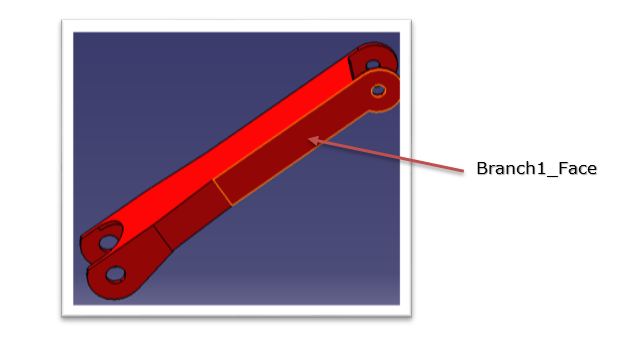
    1. In the image displayed below, Face is selected as an element to publish which is highlighted in the geometry.
p8

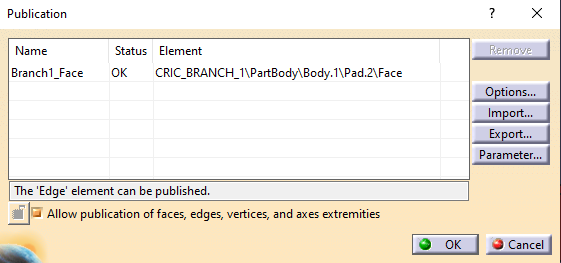
    1. Rename the face as Branch1_Face. The face is published as
p3

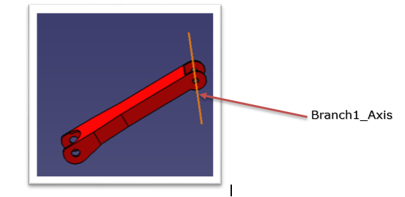
To publish axes, right-click cylindrical faces and select Other Selection à Axis.

Rename it to Branch1_Axis.
sdf

    1. During the use of Publication, one can decide to rename or not rename the elements that are published by using Options menu in the dialog box. Before renaming, one of the following work modes can be set:
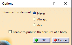
      • Never – This is the default option. It will not allow to rename the published element.
      • Always – One can always rename the published element.
      • Ask – The application will ask whether to rename the published element or not.

p5

Note:

    • One can rename any element except for axes, edges and faces.
    • Exclamation mark is not allowed for renaming the published element.
    1. Check Ask and click OK to exit.

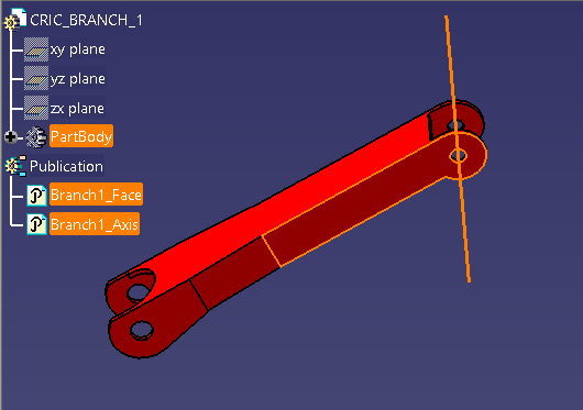
As shown in the following image, a face and an axis of the CRIC_Branch_1 part has been published.
p6

Advantages of using Publications in CATIA V5.

 Publishing geometry has the following advantages:

    • Published geometry can be given a name which can easily be recognized e.g. in case of publishing edges, faces etc.
    • Publications are used to make a particular geometry easily accessible from the specification tree.
    • By using the required setting, only published elements can be used as an external reference if it is the requirement.
    • Publications are very helpful when replacing one component of an assembly with another because published elements having the same name are automatically reconnected during replacement. Else one would have to reconnect them manually if they were not published.
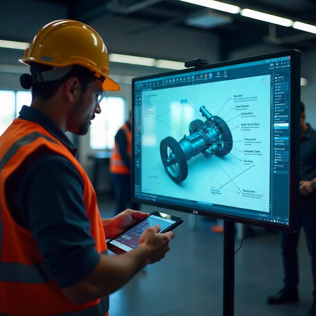
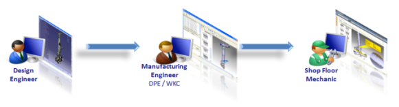
Save Time, Cost and Improve Accuracy of your Work Instructions by adopting 3D Model-based approach

While there are multiple Work Instructions formats, for the past few years, there is a debate on the suitability and applicability of the appropriate format. This might be the time to put that debate to rest. There are many studies which show that something which is graphic and in pictorial form is more likely to be understood and easier to use. Work Instructions are among the first things which are digitized in Industry 4.0. With the use of right application, it will be an important step for digital transformation and also have a significant impact on manufacturing operations.

What if one could deliver common Work Instructions of multiple configurations to the right people at the right time?

Shop floor deliverables have become much more accurate and precise by using 3D Work Instructions. This was not the case earlier. In the absence of 3D Work Instructions, organizations faced significant loss of time by imparting training to their workforce or making them understand how the system works. It is also not very easy to maintain Work Instructions on paper or in file format. If one compares this with digital Work Instructions, one can see that it is very easy to maintain and minimize the efforts of engineers. These Instructions can be reused for different configurations as well as for different locations considering how rapidly manufacturing processes get changed.

DELMIA Work Instructions help in making:

  1. Operations in sequence
  2. Standard links
  3. Part and tool list
  4. Product and tool list
  5. Markup visual aids

One can also make Work Instructions for machine maintenance, which is majorly of two types:

  1. Preventive Maintenance (PM) includes inspections, condition monitoring, services, and testing.
  2. Corrective Maintenance includes repairs and replacements.

Preventive Maintenance is further broadly classified into three types of tasks:

On-condition tasks – On-condition tasks are used to address specific failure modes of equipment and in most cases seek to determine the condition of equipment and more specifically identifying potential failures associated with the failure mode. This can include inspections, measurements, and condition monitoring.

  1. Fixed interval tasks – Fixed interval tasks are used to address failure modes where the wear-out or failure life is well known and the tasks are performed irrespective of the prevailing condition. These include component change outs that are either refurbished or discarded (as determined during the earlier task development stage), cleaning, lubrication, calibration, and adjustments.
  2. Failure finding tasks – These are used to detect failures of protective devices. These can be safety-related devices or equipment protection devices. Tasks can include manually activating the device such as pull wires on conveyors or limit switches, artificially simulating conditions for the devices such as using synthetic smoke to test smoke detectors, restricting flow for low flow switches, lowering, or raising levels for level switches, injecting electrical current into high voltage overloads or circuit breakers.

Corrective Maintenance Work Instructions

Work Instructions are only used for complex or difficult corrective maintenance. OEMs often provide detailed instructions for maintenance of their equipment in the form of workshop manuals or procedures.

Where a Work Instruction is required, it should contain:

  • The equipment number and description at the lowest level in the equipment hierarchy.
  • Equipment isolation and preparation for maintenance (such as releasing stored hydraulic pressure).
  • A sequence and description of the tasks in sufficient detail so that there is no misunderstanding of what is required.
  • Specifications pertaining to individual tasks (such as bolt tightening torque requirements).
  • Warnings of potential hazards for the maintainer.
  • Damage to the equipment while undertaking particular tasks.
  • Tips on how best to undertake the task (such as positioning or handling).
  • Pictures and diagrams can be very useful, particularly if uncertainty is likely while performing the task.
  • Parts required including Stock Number or Manufacturer Number.
  • Specific tools required.

DELMIA 3D – Work Instructions are increasingly getting adopted by organizations in the present digitized world. At EDS Technologies, we help organizations discover the value of this application and ensure a seamless integration with their digital manufacturing processes. We also encourage to our manufacturing customers to start with DELMIA 3D – Work Instructions which will reduce their time and effort significantly and thereby increase efficiency.

blog2

Innovative Design with 3DEXPERIENCE on Cloud

Consumer’s expectation to experience a product before buying has triggered organizations to adopt new solutions for developing innovative products by unleashing creativity and brainstorming ideas in their ecosystem with a collaborative platform.

Industrial designers do real-time collaboration with other teams like engineering, marketing, and production. They propose their ideas, take feedbacks, incorporate changes, and improve the product quality.

Mechanical engineers explore innovative solutions and workable concepts for the detailed design. They try and enhance design of mechanical parts, overcome new challenges by enriching their design with sophisticated and complex surfaces and by benefitting from existing designs. They even use engineered parts and explore new manufacturing possibilities by editing specific features and drill down to rough components. 3DEXPERIENCE on Cloud offers multiple applications with industry leading features for detailed mechanical design of the rough parts and also check the feasibility to ensure proper manufacturing requirements are met.

Today, I would like to discuss 3DEXPERIENCE Natural Shape which enables forging industry to create and redesign innovative products and tooling.

3DEXPERIENCE Natural Shape enables inverse design for precision forging

Today, the forging industry has replaced the conventional forging process (forging with flash) by precision forging enabling them to manufacture forging parts in large quantities with lower cost. This benefit is in terms of enhanced geometrical and dimensional accuracy. This approach tries to create a net shape or at least a near-net shape part due to which process design, die design and die manufacturing have become critical for forging suppliers.

edst-b1

Recently, many forging suppliers faced the challenge of inverse design. We analyzed this challenge and realized that they are receiving non-history CAD data of finished forging part as input. Thus, the designers adopted reverse approach starting from the geometry of the finished forging part and then proceeded to determine the geometry of the work piece from previous stages (intermediate stages) going backwards towards the starting billet. 3DEXPERIENCE CATIA Natural Shape allows direct manipulation of the 3D geometry; creating and modifying volumes and surfaces; edit any other CAD formats; precise geometry definition; respecting mechanical design semantic like fillets, drafts, patterns, etc. Natural Shape unified user interface allows designers to accelerate their design with natural manipulations and contextual interactions. Furthermore, designers can go ahead with the detailed design process; they can also benefit from all the CATIA modeler capabilities, including functional design, advanced feature-based approach, tolerant modeling capabilities and knowledge-ware design automation.

Natural Shape, Natural Sketch and Natural Assembly applications of 3DEXPERIENCE on Cloud provide today’s industry a complete and unified design solution to enhance creativity and design quality. With these and other 3DEXPERIENCE on Cloud apps, one can bring together all aspects of their customer business on a single cloud-based platform to increase collaboration, improve execution and accelerate innovation.

3DEXPERIENCE Cloud platform enables industries to design innovative products by:

  • Imagining and exploring creative styling ideas in 3D with 3D sketching.
  • Creating and fine-tuning 3D shapes and surfaces with integrated surfacing technologies.
  • Experiencing design intent in the context of high-end real-time visualization and immersive experience.
  • Presenting and making design decisions with interactive real-time experience and reducing decision-making time using concurrent engineering.
  • Designing complex mechanical parts.
  • Avoiding repetitive tasks by reusing existing design assets.
  • Exploring innovative solutions and workable concepts for detailed design.
  • Collaborating with your team and others.
  • Working on large assemblies.
  • Being more efficient in everyday tasks.
  • Reducing design and manufacturing errors with process-oriented features.

Common CATIA V5 Shortcuts & Customization

For any CAD software, Model manipulation options are very important to improve the productivity & for ease of use. This article will introduce you to all these options below.

Model Manipulation with Mouse

Function Options using your Mouse
Pan Hold Middle Mouse B
Zoom Hold Middle Mouse B + Click Right B or

Hold Middle Mouse B + Click Left B

Rotate Hold Middle Mouse B + Hold Right B or

Hold Middle Mouse B + Hold Left B


Model Manipulation with Keyboard

Function Option using your Keyboard
Pan CTRL + RIGHT Arrow Key: Move the model to the right

CTRL + LEFT Arrow Key: Move the model to the Left

CTRL + TOP Arrow Key: Move the model to the Top

CTRL + BOTTOM Arrow Key: Move the model to the Bottom

Zoom CTRL + PAGE UP: ZOOM IN the model

CTRL + PAGE DOWN: ZOOM OUT the model

Rotate SHIFT + LEFT Arrow Key: rotate to the left

SHIFT + RIGHT Arrow Key: rotate to the right

SHIFT + UP Arrow Key: rotate upward

SHIFT + DOWN Arrow Key: rotate downward

Listed below are the CATIA V5 shortcut keys that users need to know.

Esc: Abort the current process or exit the current dialog box (when there is one)

  • F1: Get CATIA V5 assistance by launching the contextual help documentation
  • F3: Toggle specification tree display on and off
  • SHIFT – F1: Context assistance (Get help on toolbar icons)
  • SHIFT – F2: Toggle the specification tree overview on and off – opens an overview on specifications tree in a new window.
  • SHIFT – F3: Structure tree activate around e.g. character size to modify (activate the graph if the model is active and inversely)
  • ALT + F8: Macros start
  • ALT + F11: Visual basic editor
  • CTRL + SHIFT + Right arrow: ROTATE the model Clockwise
  • CTRL + SHIFT + LEFT arrow: ROTATE the model Anti Clockwise
  • CTRL + Tab: switch between the different windows (swap active document windows)
  • CTRL + N: New document open
  • CTRL + O: Document open
  • CTRL + S: Document save
  • CTRL + P: Document print
  • CTRL + F: Search
  • CTRL + U: Update
  • CTRL + X: Cut out
  • CTRL + V: Insert
  • CTRL + Y: Redo
  • CTRL + Z: Undo
  • CTRL + G: Selection Sets
  • ALT + Enter: Properties

Did you know that you can improve your CATIA speed and efficiency by using both hands? One hand can work the mouse while the other can use keyboard shortcuts.

Customize the Commands:

You can also create your own shortcuts for the frequently required commands by customizing them.

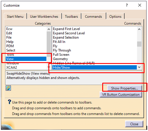
Tools>Customize

k1a


Select the Command Tab. Select the appropriate Categories and select the command (Hide/Show) which you want to create short key.

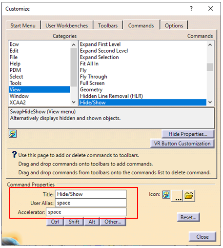
Click Show Properties button. Type the key which you want to use as shortcut key. In this example space bar key is used in the Accelerator field.

k2a

Now whenever you will press Space Bar key it will allow you to Hide/Show the selected elements.

Power input mode

 The power input box is located in the bottom right corner of the status bar:

Power input mode is a user-friendly productivity assistant allowing you to:

k3

  • Enter numeric data more easily in editable fields and spinners (but cannot be used in combo lists); as such, it is intended as an alternative to typing values in dialog boxes (dialog boxes are however still available).
  • Enter commands directly (by typing the c: followed by the name of the command).
  • Entering selection queries using the query language available when using Edit > Search.

Power input is available in certain (but not all) application commands. Note also that prefixes used to run commands or selection queries vary according to the language.

To activate power input mode, select Tools > Options, click the General tab, and click the P2 option, then restart your session.

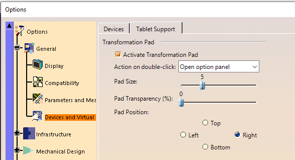
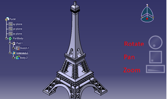
Activate Action Pad

This task explains how to set up pad options in order to perform viewing operations using the Tablet Pen on a Tablet PC. Note that you can use the pad to visualize both 2D and 3D objects

Tools>Options>General>Devices & Virtual Reality

If this option is selected, it means that the pad display is activated in the geometry area. By default, the pad is displayed to the right as shown below:

k4 k5

Launching CATIA 3DEXPERIENCE on CLOUD in the Administrative mode

To set drafting standards and set user default catsettings for 3DEXPERIENCE CATIA we need to launch CATIA in Administration mode (Admin mode). It can also allow us to lock certain software settings. For 3DEXPERIENCE CLOUD this can be accomplished using the following steps.

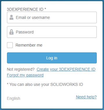
  •  Log in to 3DEXPERIENCE Platform with required credentials.

z1

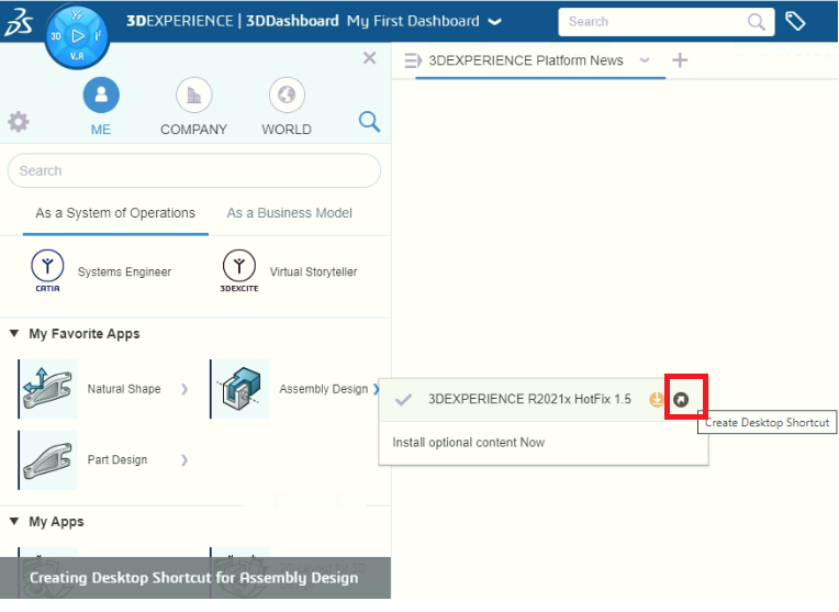
  • Click on the 3DEXPERIENCE/ IfWe Compass.
  •  Select the small black/ grey arrow just to the right of one of the 3D Modeling apps (for example, Assembly Design).
  • A menu opens showing the available tenants as well as the 3DEXPERIENCE level being used.
  • From the menu, select the “Create Desktop Shortcut” icon (grey/ white arrow just to the right of the 3DEXPERIENCE level name).

z2

  • A Shortcut for the selected app is now placed on the Windows desktop.

z3

  • Open the contextual menu (Right-mouse-click) on the shortcut and select Properties.

z4

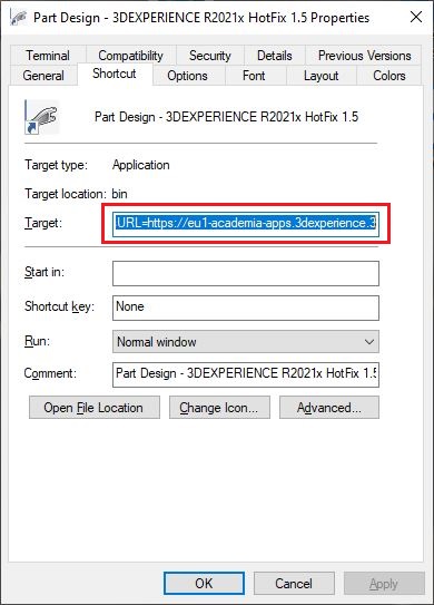
Copy the entire text string from the ‘Target’ field, located on the Shortcut tab of the Properties menu.

  • Create a new Text file on the Desktop and name it with the extension of .bat, instead of .txt. Paste the contents from Step 7 into the .bat file.
  • Launch the Desktop Shortcut (not the .bat file at this point).
  • When the login window is presented, cancel it by selecting on the X in the upper right corner of the window.
  • Go to the CATTemp directory (for example, C:\Users\username\AppData\Local\DassaultSystemes\CATTemp).
  • Open the latest Session Info File (for example, SessionInfoFile_username_d070_h13m21_p13584_0.txt) from the CATTemp directory. Then scroll to the bottom of the Session Info File. Here, you will find the list of Arguments used for launching the application.
  • Add any missing flags/ arguments shown in the Session Info file that were not included in the shortcut target from Step 8 into the batch file from Step 9.
    Note that steps 7-14 are required, that is, creation of a batch file (.bat), because the Desktop shortcut ‘Target’ field only allows 259 characters due to a Microsoft Windows hard coded limit.
  • In the Batch file add “-admin”, but without the quotes, just after exe of “3DEXPERIENCE.exe”
    (for example, “C:\Program Files\Dassault Systemes\B423\win_b64\code\bin\CATSTART.exe” -run “3DEXPERIENCE.exe -admin” -object “-Url=https://tenant_name-tenant_path:port/enovia -MyAppsURL=https://tenant_path:port/enovia/resources/AppsMngt -tenant=tenant_name)
  •  Save the Batch file ensuring that it remains as a .bat and not a .txt file.
  • Open the 3DEXPERIENCE CATEnv.txt file.
    Enter a directory path for the “CATCollectionStandard=” variable. (for example, CATCollectionStandard=C:\Users\user_name\Documents\ My3DEXP_CATCollectionStandardDirectory). Enter a directory path for the “CATReferenceSettingPath=” variable (for example, C:\Users\user_name\LockSettings).
  • Double-click the Batch (.bat) file created in Step 9.
  • Specify the your 3DEXPERIENCE login credentials.
  • To be able to modify & create drafting standards you need to log in as owner role.
  • This will launch the 3DEXPERIENCE CATIA in Admin mode with the ability to set activity of locks in Me>Preferences and Me>Standards for setting drafting standards as per the requirement.

Role of Internet of Things (IoT), Machine Learning (ML), Artificial Intelligence (AI) in manufacturing industries

The manufacturing organizations are facing a number of challenges to sustain and grow due to the current crisis arising out of the pandemic. The organizations are looking at various options to tide over the crisis they face today. Some of them are looking within to improve the operational efficiency and customer quality by optimizing the resources, cautious investment, and utilizing the existing solutions & technologies effectively. Others are considering this as an opportunity to bring in new technologies and remove the inefficiencies in their systems.

The technologies like Internet of Things (IoT), Machine Learning (ML), Artificial Intelligence (AI), Robotics & Shop floor simulation, etc. have started to play an important role in the day-to-day operations of manufacturing industries. Many organizations in India are investing in these technologies, especially the IoT platforms within the shop floor to streamline and automate the processes and deliver on goals. The Machine to Machine & Resource connectivity, Automation across the production/assembly line and Robotics & Shop Floor Simulation in a virtual environment are some of the important areas that are being addressed immediately across many of the customer sites in India.

Industries are validating the technology players across various parameters in their selection criteria with cost as the primary factor followed by technical capabilities, service provider capabilities, long term support, security, scalability, and flexibility that plays a significant role in choosing the IoT platform or ML or AI Technology.

Many IoT players in India are making a big impact on manufacturing industries right from the large scale to SME sectors, in recent times, with customers coming forward to embrace the technology. Several companies have started implementing the IoT platform and those who implemented are getting to realize the benefits greatly.

a1

Some of the real values and benefits that manufacturing industries are getting to realize after adopting these renowned technologies are:

  • Achieve Customer Centricity

Customer satisfaction is the primary factor that every business must focus on. The IoT advancements like mobile card readers, smart trackers, etc., will help businesses to enhance their customer experience.

  • Increase Productivity

AI-driven robots work for 24-hours a day and minimize the manufacturing operational expenditure while increasing productivity. IoT helps to gather real-time data from multiple machines, which results in improved performance and reduced workload. IoT also helps in offering just-in-time training for employees, reduce mismatch of skills, and improve labor efficiency while enhancing productivity.

  • Cost Saving

These advanced technologies provide predictive analytics and real-time diagnostics which helps to drive down the maintenance costs. Predictive maintenance allows manufactures to predict the system or machine failures and helps in preventing manufacturing downtimes. The minimized downtimes, process efficiencies, and optimum asset utilization saves your investments.

  • Increase Business Opportunities

IoT enables new business opportunities and allow organizations to benefit from the revenue streams generated by exceptional business models and services. These emerging technologies empower companies to build strong business cases, minimize their time to market, and boost ROIs. They have the potential to transform the way businesses approach the world and open doors for numerous opportunities.

  • New revenue streams

The time to roll out new products or services in the market is always swift and efficient with the help of the latest technologies. They help businesses predict customer behaviour and interests, which enables them to quickly plan and deliver the new revenue-generating offerings.

EDS Technologies, a platinum partner of Dassault Systemes is helping companies to discover ways to overcome their manufacturing challenges owing to the current pandemic and market conditions to rebound back stronger, leaner and with increased agility utilizing the 3DEXPERIENCE platform. You can leave a message at edst@edstechnologies.com  in case you wish to talk to our industry consultant on this.

Subscribe to our newsletter

Get all the latest information on Events, Sales and Offers.