How 3DEXPERIENCE On Cloud Adoption Helps Maintain Digital Continuity in Organizations

“Cloud” has been the buzzword for the past few years. Many companies have identified the upcoming business needs and challenges and have adapted by shifting to On-Cloud solutions. Decision makers need to be always connected digitally with the respective stakeholders.

The main conundrum now is that how can design and manufacturing be connected through cloud. Based on interactions with customers, some of the challenges perceived by them are listed below:

  1. How can digital continuity be maintained from RFQ to marketing and sales?
  2. How to connect service providers and respective stakeholders all the time by maintaining the same data connectivity?
  3. How to perform design, reviews, manage projects, conduct live digital meetings and so on?

Below are the 10 ways how the adoption of 3DEXPERIENCE On Cloud from Dassault Systèmes has helped customers tackle these challenges and maintain the digital continuity.

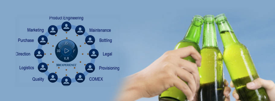
  1. 3DEXPERIENCE On Cloud provides a holistic real-time visibility of business to all stakeholders connecting people, ideas, data and solutions in a single collaborative and interactive environment.
  2. Cloud enables everyone involved in the project to interact, imagine, design, simulate and deliver.
  3. With the help of Cloud, collecting, importing and sharing project data can be done immediately to the respective team. Data can be stored in 3DSpace, a centralized server of Dassault Systèmes maintained by Amazon Web Services.
  4. Assigning and managing tasks or projects between different stakeholders and tracking the projects through web can be done by Cloud.
  5. Design reviews can be done on the fly irrespective of the location.
  6. Using Market Place and Part Supply accessibility, order can be sent to the certified suppliers or vendors.
  7. The Cloud solution is cost effective and provides immediate access to users.
  8. Cloud is adaptable, flexible and scalable with automatic updates.
  9. It enables faster collaboration by enabling accessibility anywhere, anytime and on any device.
  10. It is secure with protected environment.


The cloud-based 3DEXPERIENCE platform provides access to a growing portfolio of solutions that work together seamlessly. Some of them are discussed below in detail:

  1. Collaborative Business Innovator
    • Express innovative and creative ideas with communities seamlessly.
    • Digital connect with live dashboards assists in collaboration.
    • Can sketch and share ideas on the fly with the help of this solution.
    • Instant contribution makes the discussion more interactive and expedites decision making.

    x1

  1. Project Planner
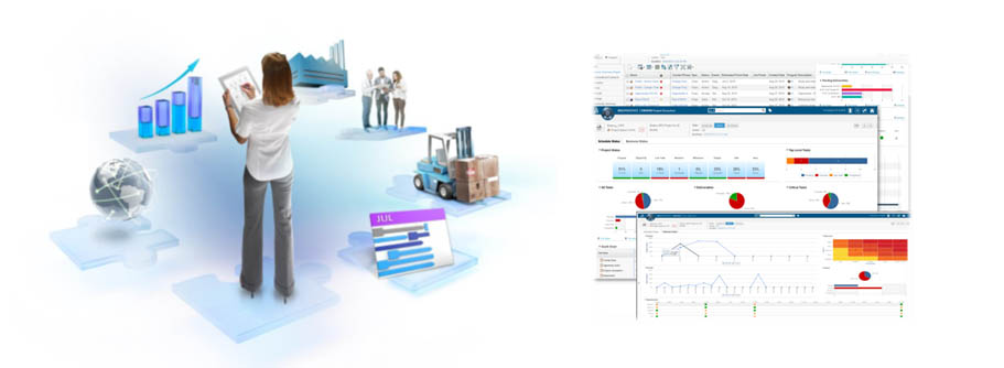
    • Collaborative project planning with real time KPI monitoring.
    • Assign tasks to the respective users with deadlines and tracking the same with seamless integration.
    • Project planner dashboard can be accessed through mobiles, iPad and PCs anywhere anytime.

    x2

  1. 3D Innovator
    • Can do web based parametric design which helps to design anywhere, anytime and on any device.
    • Design and assemble parts, design guidance for topology, non-parametric optimization and accesibility to marketplace to 3D print the components.
    • Can manage complete PLM which improves efficiency, quality, productivity and innovation

    x3

  2. Lean Team Player

    Manufacturing teams can conduct digital meetings, track with the inbuilt lean principles with virtual models, process and resources

    x2

How does Adoption of CATIA 3D Master benefit Design and Manufacturing Companies?

z1

The emerging trends in the market and the progression towards Industry 4.0 indicate an increased need for “Model Based Definition” (MBD) or 3D GD&T in design and manufacturing companies.

GD&T is used by engineers in drawings to convey design details to manufacturing teams.

With the increased adoption of Model Based Definition, engineers now place GD&T directly into 3D models instead of generating in 2D drawings. This would make 3D geometry as a “Single Source of Design Information”.

CATIA 3D Master (FTA) allows the designer to create GD&T for designed parts as well as for assemblies.

Once the FTA is done, the same data can be shared to manufacturing teams so that they can directly access the design data along with GD&T eliminating the need for traditional drawing sheets.

z2

Evolution of the Design Process:

The design process has undergone a transformation over the past 50 years. The below infographic shows the evolution of the design process from 1970 to the present day.

z3

Advantages of CATIA 3D Master (FTA):

There are many advantages in using CATIA 3D Master as compared to creating GD&T in 2D drawing sheets. Some of them are listed below:

  • Eliminates the effort to generate and update 2D documents according to the 3D geometry definitions
  • Can re-use the design from previous projects quickly
  • FTA implementation can eliminate the time taken to create the drawings
  • Since CATIA 3D Master acts as a “Single Source of Truth”, the latest version of the data is always available
  • Helps to increase the quality of manufactured products
  • Ensures compliance to international standards
  • Leads to better communication since the work flow is entirely 3D based
  • Reduces drafting time, supports paperless design and increases the collaboration with customers and suppliers

Adopting and implementing CATIA 3D Master (FTA) ensures companies to reduce design time and that the products reach the market quickly.

How a startup can thrive in the market?

Startups come up with new designs and inventions. However, qualifying them as a viable product in a short period of time and preparing them for production and commercialization has many challenges.

Some of the challenges could be:

  1. Design finalization and approvals as per industrial standards
  2. Prioritizing consumer experience
  3. Overcoming expensive physical validations
  4. Achieving the first-mover advantage
  5. Getting stabilized in the market while competing with big players

The above challenges can be addressed by a few ways. They are explained below:

  1. Startups get lot of support from the government for developing Electric Vehicles, Drones and UAVs. They should approach the right people, utilize, validate and adopt the right digital solutions at the right time to address the market demands.
  2. Adopting cloud technology is one solution which gives flexibility to the stakeholders to connect from wherever they are.
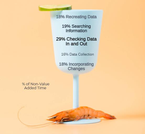
  3. Adopting model-based design solutions where design, engineering, manufacturing, marketing, purchase and finance are on the same platform which will reduce the time-to-market by eliminating all non-value-added tasks.
  4. From market study, concept design digital definition, digital Validation, process planning, product development to customer experience, it is difficult to adopt different applications by a startup and deliver the product to the market on time. To simplify and expedite the process, Industry Solutions Experience and Industry Process Experience can be opted as per startup requirements which are available in 3DEXPERIENCE platform. With this combination, design, engineering, manufacturing, governance and marketing solutions are available on a single platform with cloud environment


Industry Solutions Experience and Industry Process Experience are beneficial to startups. They are explained below by taking the examples of EV and Aero-related startups:

  1. There are few of the Industry Process Experience as a package like ELECTRO MOBILITY ACCELERATOR for the EV startups. The complete workflow is given below:
    a1
    • Over 50 percent of programs in Aero-related startups (UAVs, drones) miss their deadlines. Programs are often delayed due to issues being discovered during the manufacturing process that could have been prevented in the design phase. To significantly increase competitive advantage, startups can opt for Co-Design to Target solution under Mechatronics Systems Engineering or Component Functional Generative Design for Additive Manufacturing.
      a2

Composite Structure Investigation using ABAQUS Finite Element Solver

Introduction

Composite materials are less expensive and stronger in nature in comparison to conventional materials. They are formed from two or more constituent materials which are different in physical, mechanical and chemical properties. By nature, they are light in weight and extensively employed in spacecrafts, aircrafts, buildings, bridges, racing cars, bathtubs etc.

From a macroscopic point of view, composite materials are anisotropic in nature and require special tools such as numerical tool (FEM) and analytical method or mathematical tool to get insights when under failure, shock, impact or repeated cyclic stresses.

Keeping in mind the complexity and material orientation, this article captures the three-dimensional behavior of composite materials.


Geometry and Meshing

A solid homogenous part is created with internal partition and defined using offset options. Inside the solid homogenous part, a set of matrices are created.

For meshing, 8-node linear brick, reduced integration and hourglass control (C3D8R) were applied as shown in Fig 1.


img1 

Material

Elastic properties under engineering constant are defined during material assignment.

Material, name = “Composite Materials”

Elastic, type = ENGINEERING CONSTANTS

150000, 9000, 9000, 0.34, 0.34, 0.4, 5000, 5000, 5000


Loading and Boundary Conditions

The simulation is performed under static conditions. During the first step, composite structure remains at static conditions. Both sections internally and externally are under static conditions. During the second step, one side of the structure remains under ENCASTRE conditions (U1-U2-U3-UR1-UR2-UR3 = 0). The second side is experiencing a displacement of -5 mm in Z – direction to generate the stress wave propagation as shown in Fig 2. The holistic idea is to see how internal stress is propagating within the structure.

The complete analysis (Pre + Post + Solver) is simulated in ABAQUS/ CAE code.

img2

Results and Visualization

Stress distribution within the internal and external structure is calculated using path feature. Internal matrix experiences slightly lesser tensile stress when compared to external structure under Encastre conditions. Internal matrix which is close to Encastre conditions experiences higher compressive stress.

img3

img3

img5


Mises stress components at integration points

img6

Mises stress components at integration points in S33 direction

img7

Conclusion

The behavior of composite materials is studied using ABAQUS FEM Code. The main objective is to see how the stresses are distributed within the structure (Matrix). ABAQUS helps in predicting the behavior of composite materials subjected to displacement. The approach mentioned in this article can be used in a more complex way by varying the internal matrix dimensions. The matrix can be placed in dissimilar alignment also.

ABAQUS offers higher degree of autonomy in pre- and post-processing. It helps in gaining insights when composite materials are subjected to different conditions.

Why Data Driven CAD is Preferred over File Based CAD

The need for PLM integration with CAD is one of the key concerns of any engineering company to stay competitive and launch the product in the market in a short duration.

If you are in the process of replacing your file-based CAD system with data-driven CAD, then Dassault Systèmes’ 3DEXPERIENCE platform is the way to go.

CAD blog1

3DEXPERIENCE platform boasts of distinct features like cloud based, data driven and all-in-one PLM experience which will ease any typical workflow and support faster go-to market strategy.

3DEXPERIENCE is available on Premise and also on Cloud. This eliminates file-based data storage which has an impact on real time digital continuity.

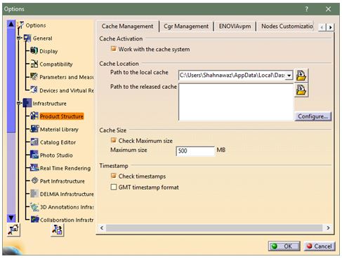
One of the unique values of having database driven CAD system is that it gives access to store the data in the server and thereby restricts saving it locally. All the stakeholders can access the data based on their roles which is assigned by the admin. It also allows external suppliers and customers to connect to the platform, access relevant data, collaborate and accomplish the task thereby expediting decision making.

CAD blog2

Often many projects get delayed or overshoots budget because of the discontinuity of the digital data flow. The major advantage of a data driven platform is to access a “single source of truth” which means if any data is modified, then it is available for all the stakeholders in real time. They will always have the access to updated data.

Imagine that there are multiple work locations and team members working on the same project. Any changes in part or assembly will automatically be updated to all the stakeholders no matter where they are working.

Analysis is one of the crucial areas which can accelerate the product launch. More often, products are validated in a digital platform instead of a physical test. In this scenario, design data should be imported to analysis software and any change in the design has to be communicated to the design team. Once the design changes are done, the design team needs to push data to analysis software manually. This process often leads to data loss and is also time consuming. However, with 3DEXPERIENCE platform, all the stakeholders of the project (analysis team is also one of the stakeholders) can get real time data without any data transfer out of the platform. Since the data is stored in server, all the users will have access to the latest data with respect to the assigned project.

The CATIA 3DEXPERIENCE platform is much more than a CAD software. It also manages end-to-end workflow, deliverables and project deadlines. Since the platform is data driven, project managers can access all the data which is related to the project and make better decisions so as to accelerate the product launch to the market.

3DEXPERIENCE has two different interfaces: web and native interface. Social, collaborative and information intelligence apps will work in web interface without any installation. The native apps however require installation. All the 3D modelling and simulation apps such as CATIA, SIMULIA and DELMIA are part of native apps.

Today the market is more demanding and competitive. 3DEXPERIENCE will definitely help companies to stay competitive and create sustainable growth.

How to perform Geotechnical Analysis of Soil using ABAQUS

The analysis of geotechnical problems is rather complex due to stress dependent material behavior and varying stiffness for loading and unloading conditions. Generally, soil has three different phases which are soil skeleton, pore air and pore water which often lead to complex interaction mechanism. Also, large deformation of soil continuum is observed under loading. Such complex behavior, boundary and material modelling can easily be found out and addressed by ABAQUS.

This blog mainly focuses on ABAQUS capabilities of soil modelling, material modelling, complex loading analysis, boundary modelling and analysis procedures used in geo-mechanics by taking the example of a laterally loaded pile.

Characteristics of Soil:

How to perform Geotechnical Analysis of Soil using ABAQUS-1

The typical granular soil composition is of three components viz solid, liquid, and gas. The solid components of soil are solid grains (resultant of weathered rocks). The liquid component is usually pore water (pore fluid), and the gas component is usually air. The gaps between the solid particles are called voids.

When soil is loaded, the pressure in pore fluid gets modified due to which the pore fluid flows and leads to the deformation of soil over a period of time. This deformation of soil can be analyzed by using mechanical and permeability properties of soil along with pore pressure boundary condition in ABAQUS.

Loading Conditions:

Material behavior of the soil is rather complex when compared with other engineering materials. Soil can be differentiated like granular soil (sand and gravel) and soft soil (clay or silts). When granular soils are loaded slowly, there will be a change in volume which results in excessive pore pressure that dissipates rapidly due to high permeability and is called as “Drained Loading”.

On the other hand, when soft soils are loaded, it generates excess pressure which is entrapped inside the pores because of low permeability. This condition is known as “Undrained Loading”. Generally, both loading conditions can be carried out in laboratory by using Tri-Axial test setup. Therefore, in numerous simulations, this complex behavior has to be taken into account.

Material Models:

Several material models are available in ABAQUS including elastic, plastic, pore fluid, concrete damage plasticity, concrete smeared cracking and plasticity models as discussed below.

How to perform Geotechnical Analysis of Soil using ABAQUS-2

ABAQUS built-in material model can deal with applications where fully coupled conditions are needed to simulate. There are exceptions where large deformation needs to be modelled with special techniques such as Discrete Element Techniques (DEM). Also, user defined material can be incorporated with VUMAT, UMAT framework. For laterally loaded pile, the following properties are used.

How to perform Geotechnical Analysis of Soil using ABAQUS-3

Contact Interaction for Geotechnical problem:

ABAQUS provides two algorithms for modeling contact interaction:

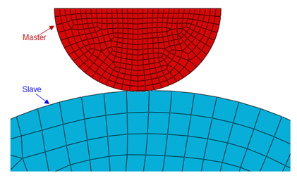
  1. Contact pair algorithm – it is used where every possible surface pair has to define contact interaction including surface which may come in self contact. It is also based on master-slave definition.
  2. General contact algorithm – it allows to define many or all regions with single interaction properties. This algorithm automatically decides master-slave surfaces.

ABAQUS also gives flexibility to find contact surface automatically within chosen parts or whole model.

How to perform Geotechnical Analysis of Soil using ABAQUS-4

In geotechnical analysis, where blast loading is carried out to analyze the structure load bearing capability, Eulerian domain needs to be defined. In such scenario, general contact has to define and it works very efficiently.

Element Selection:

To model fully or partially saturated fluid flow through a deforming porous medium, ABAQUS provides Pore Pressure Element type which can be used for soil and geostatic analysis. These elements have both displacement and pore pressure degrees of freedom. In second-order elements, the pore pressure degrees of freedom are active only at the corner nodes. Pore Pressure Elements are available for plane strain, axisymmetric, axisymmetric-asymmetric and for three dimensional problems.

How to perform Geotechnical Analysis of Soil using ABAQUS-5

Analysis Procedure:

ABAQUS Standard provides two different procedures to analyze the soil problems viz “Geostatic” & “Soil”. Also, soil like material, in case of large deformation, can be simulated using special techniques like

  1. Coupled Eulerian-LaGrangian Techniques (CEL)
  2. Smoothed Particle Hydrodynamics Techniques (SPH)
  3. Discrete Element Techniques (DEM)

Above techniques can be used for offshore foundation, crushing of soft rocks, mining & agricultural industries respectively. For laterally loaded pile the “Geostatic” & “Soil” procedures are used for analysis.

“Geostatic” procedure is normally used as the first step of a geotechnical analysis; in such cases gravity loads, initial stress state, void ratio distribution or saturation are applied during this step. Ideally, the loads and initial stresses should exactly equilibrate and produce zero deformations. The geostatic procedure requires that the initial stresses are close to the equilibrium state; the displacements corresponding to the equilibrium state might be large. “Soil” procedure is used to specify transient (consolidation) or steady-state response analysis of partially or fully saturated fluid-filled porous media.

Subscribe to our newsletter

Get all the latest information on Events, Sales and Offers.